
Secondary battery

a secondary battery and battery technology, applied in the field of batteries, can solve the problems of difficult promotion of energy density of cells and deeper uneven points formed on current collectors, and achieve the effects of promoting energy density of cells, reducing thickness of cells finally formed, and reducing thickness of cells

Active Publication Date: 2017-07-20
NINGDE AMPEREX TECH
View PDF3 Cites 5 Cited by
  • Summary
  • Abstract
  • Description
  • Claims
  • Application Information

AI Technical Summary

Benefits of technology

This patent aims to provide a secondary battery with several benefits. The present disclosure reduces the thickness of the secondary battery cell while improving its energy density and overcurrent sectional area of the electrode tab. Specifically, the thickness of the second positive electrode tab and the second negative electrode tab ensures strength and reduces the thickness of the cell, while the width of the second positive electrode tab and the second negative electrode tab increases the overcurrent sectional area. These changes ultimately result in a thinner battery with increased energy density and improved performance.

Problems solved by technology

A thickness of an area where the electrode tab is welded is the maximum thickness in the wound type cell due to this superimposed thickness of the electrode tab, and because the thickness of the electrode tab is difficult to decrease further, the energy density of the cell is difficult to promote further.
Therefore, the problem existing in the existing process is: 1. The thickness of the electrode tab is larger, so the electrode tab occupies a larger space of the cell in a thickness direction; 2. It needs to bond adhesive tapes above the both sides of the part where the electrode tab and the current collector are welded together, so the adhesive tapes also occupy a larger space of the cell in thickness direction; 3. Due to the larger thickness of the electrode tab, it has to use a bigger welding head to achieve ultrasonic welding, which leads to deeper uneven points formed on the current collector.

Method used


Image

  • Secondary battery
  • Secondary battery
  • Secondary battery

Examples


Embodiment Construction

:

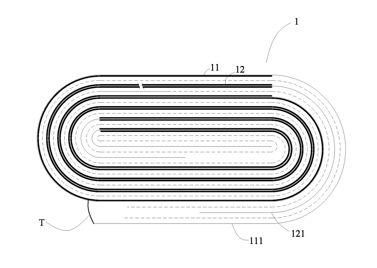
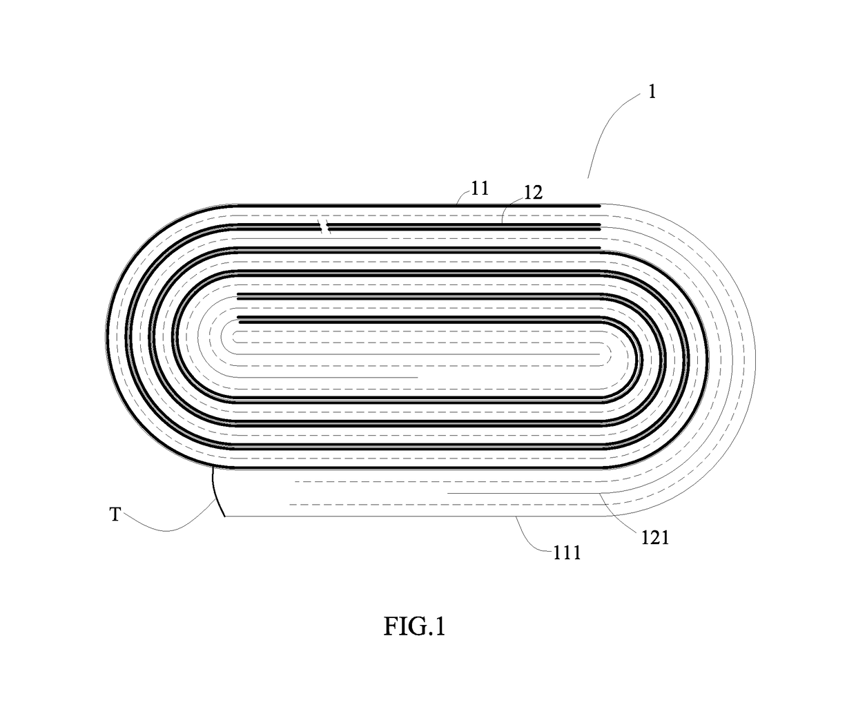
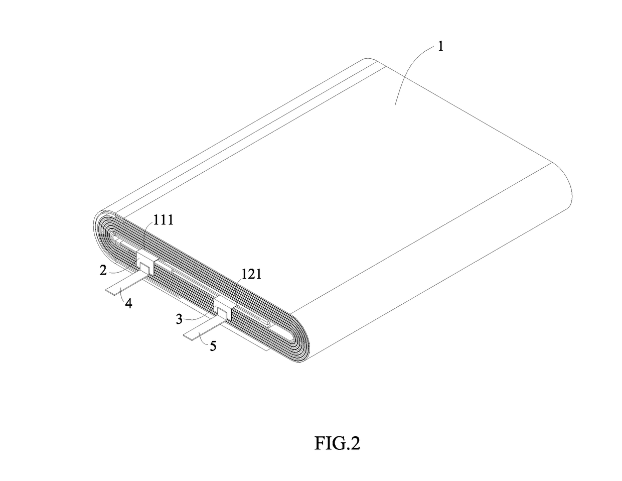
[0019]1 cell[0020]11 positive electrode plate[0021]111 positive current collector[0022]12 negative electrode plate[0023]121 negative current collector[0024]2 first positive electrode tab[0025]3 first negative electrode tab[0026]4 second positive electrode tab[0027]5 second negative electrode tab[0028]P packaging bag[0029]S1 first surface[0030]S2 first back surface[0031]S3 second surface[0032]S4 second back surface[0033]T single-sided adhesive tape

DETAILED DESCRIPTION

[0034]Hereinafter a secondary battery according to the present disclosure will be described in detail in combination with the figures.

[0035]Referring to FIGS. 1-8, a secondary battery according to the present disclosure comprises a cell 1.

[0036]The cell 1 comprises a positive electrode plate 11 having a positive current collector 111 and a negative electrode plate 12 having a negative current collector 121.

[0037]The secondary battery according to the present disclosure further comprises: a first positive electrode tab 2...


PUM


Abstract

A secondary battery comprises a cell. The cell includes a positive electrode plate having a positive current collector and a negative electrode plate having a negative current collector. The secondary battery further includes: a first positive electrode tab and a second positive electrode tab, one end of the first positive electrode tab is fixed on and electrically connects with the positive current collector, the other end of the first positive electrode tab extends to the outside of the cell; and / or, a first negative electrode tab and a second negative electrode tab, one end of the first negative electrode tab is fixed on and electrically connects with the negative current collector, the other end of the first negative electrode tab extends to the outside of the cell, one end of the second negative electrode tab is fixed on and electrically connects with the other end of the first negative electrode tab.

Description

REFERENCE TO RELATED APPLICATIONS[0001]The present disclosure claims priority to Chinese patent application No. 201620053868.2, filed on Jan. 20, 2016, which is incorporated herein by reference in its entirety.FIELD OF THE PRESENT DISCLOSURE[0002]The present disclosure relates to a field of battery, and particularly relates to a secondary battery.BACKGROUND OF THE PRESENT DISCLOSURE[0003]With development of electronic products toward miniaturization and multi-function, the electronic products have increasingly higher requirements on energy density of a battery used thereby, which requires a cell of the battery to provide more capacity in the same space. In a secondary battery with a conventional wound type cell, both of a starting end of a positive electrode plate and a starting end of a negative electrode plate positioned at the innermost of the wound type cell each are provided with a blank current collector, the blank current collector is a part of the current collector, each sur...

Claims


Application Information

Patent Timeline
IPC IPC(8): H01M2/26H01M50/533H01M50/534H01M50/536H01M50/55H01M50/557H01M50/562
CPCH01M2220/30H01M2/263H01M4/661H01M4/75H01M10/0431Y02E60/10H01M50/557Y02P70/50H01M50/562H01M50/534H01M50/55H01M50/533
Inventor ZHU, BAOJIANYANG, HONGZENG, QIAOCAI, JIACAIXU, SHOUJIANG
Owner NINGDE AMPEREX TECH
Learn More