Liquid crystal lens unit and stereoscopic display

a stereoscopic display and liquid crystal lens technology, applied in non-linear optics, instruments, optics, etc., can solve the problems of loss of lens power, cell thickness, and increase the cost, so as to reduce the cost, the effect of increasing the lens power and reducing the cell thickness

Active Publication Date: 2014-05-15
SHENZHEN CHINA STAR OPTOELECTRONICS TECH CO LTD
View PDF4 Cites 2 Cited by
  • Summary
  • Abstract
  • Description
  • Claims
  • Application Information

AI Technical Summary

Benefits of technology

[0019]Contrast to the conventional technology, the LC lens unit and the stereoscopic display using the same in the present invention comprises the retard unit which is used for adjusting the emitted light. A polarization direction of the emitted light is perpendicular to an alignment of an electrode layer. In this way, an optical axis of liquid crystal molecules in a liquid crystal layer is in parallel with the polarization direction of the light emitted by the retard unit when voltage is not applied. That is, the optical axis of the liquid crystal molecules matches the polarization direction of the light emitted by the retard unit. So, the maximal lens power is attained with decreasing the cost resulted from the decreased cell thickness.

Problems solved by technology

However, a polarization direction of the incident light to the GRIN lens 10 not match an alignment of the liquid crystal molecules within the GRIN lens 10 causes a loss of the lens power.
In order to realize lens power, one choice is to increase the cell thickness, thereby increasing the cost as well.

Method used


Image

  • Liquid crystal lens unit and stereoscopic display
  • Liquid crystal lens unit and stereoscopic display
  • Liquid crystal lens unit and stereoscopic display

Examples


Embodiment Construction

[0028]Spatially relative terms, such as “beneath”, “below”, “lower”, “above”, “upper” and the like, may be used herein for ease of description to describe one element or feature's relationship to another element(s) or feature(s) as illustrated in the figures. It will be understood that the spatially relative terms are intended to encompass different orientations of the device in use or operation in addition to the orientation depicted in the figures.

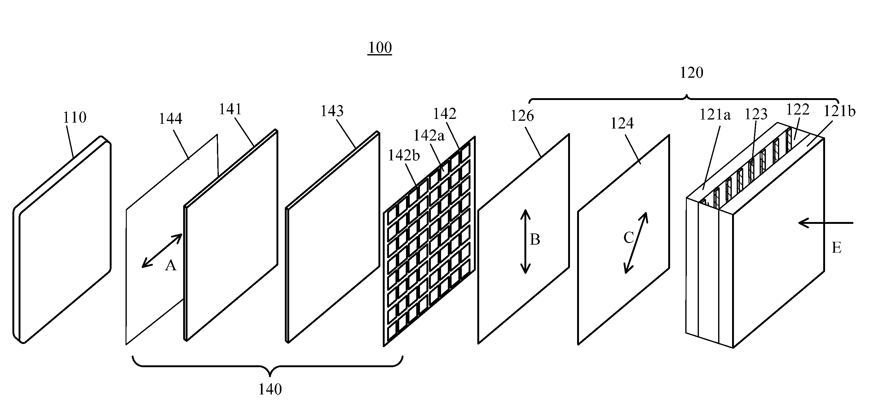
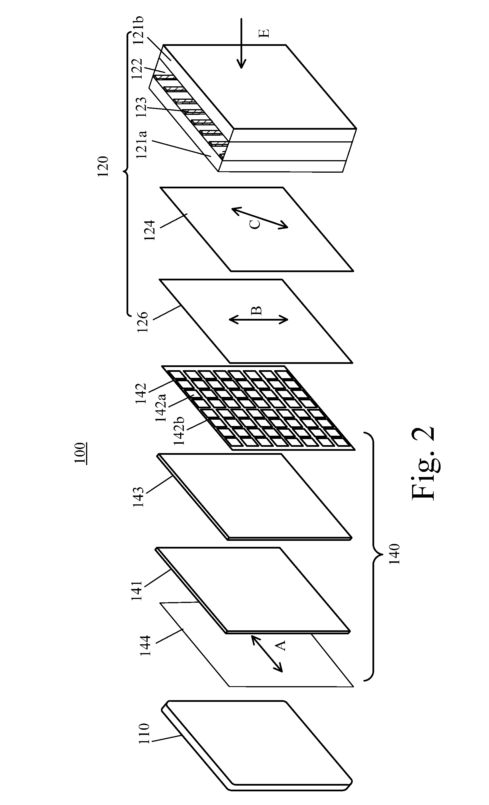
[0029]FIG. 2 is a schematic diagram showing a stereoscopic display 100 according to the present invention. A viewer can switch between 2D and 3D modes on the stereoscopic display 100 to watch 2D and 3D images. The stereoscopic display 100 comprises a backlight module 110, a display panel 140, and an LC lens unit 120.

[0030]The backlight module 110 provides a uniform planar light source for the display panel 140. The backlight module 110 can be formed by a direct-type light emitting diode (LED), a direct-type cold cathode fluorescent lamp ...


PUM

PropertyMeasurementUnit
refractive indexaaaaaaaaaa
thicknessaaaaaaaaaa
focal lengthaaaaaaaaaa

Abstract

A polarizer film is used for converting polarized light from a backlight module into light along a first direction. Multiple electrodes are disposed on a transparent substrate. Each electrode extends along a second direction different from the first direction. An alignment of liquid crystal molecules varies according to voltage applied on the electrodes. A retard unit is disposed between the transparent substrate and the polarizer film and used for converting the polarized light into light along a third direction different from the first and second direction. A polarization direction of the emitted light is perpendicular to an alignment of an electrode layer. In this way, an optical axis of the liquid crystal molecules matches the polarization direction of the light from the retard unit when voltage is not applied. So, the maximal lens power is attained with decreasing the cost resulted from the decreased thickness of the liquid crystal layer.

Description

BACKGROUND OF THE INVENTION[0001]1. Field of the Invention[0002]The present invention relates to a liquid crystal lens (LC lens) unit and a stereoscopic display using the same, and more particularly, to an LC lens unit having high lens power and a stereoscopic display using the same.[0003]2. Description of the Prior Art[0004]Real-world images are perceived by the human eyes, and further, so-called three-dimensional (3D) images are perceived by the human brain depending on an apparent displacement of an object viewed along two different lines of sight. Such a displacement or a spatial difference is called parallax. A so-called 3D display device, simulating human vision to form different viewing angles, is capable of conveying 3D images to the viewer. The 3D display device produces two different 2D images with parallax, one for the viewer's right eye and the other for the left eye. Afterwards, the viewer's brain perceives these two different 2D images as a 3D image.[0005]Nowadays, the...

Claims


Application Information

Patent Timeline
Patent Type & Authority Applications(United States)
IPC IPC(8): G02F1/1335G02F1/13G02B30/28
CPCG02F1/1313G02F1/133504G02F1/29G02F1/133638G02F1/294G02B30/28G02B30/27
Inventor CHEN, CHIH-WENHSIAO, CHIA-CHIANG
Owner SHENZHEN CHINA STAR OPTOELECTRONICS TECH CO LTD
Why Eureka
Try Eureka