Print system

a printing system and printing technology, applied in the field of printing systems, can solve the problems of sheet curving, sheet curving, and increase the size of the apparatus, and achieve the effect of increasing the transport efficiency of the medium

Active Publication Date: 2017-07-27
SEIKO EPSON CORP
View PDF3 Cites 4 Cited by
  • Summary
  • Abstract
  • Description
  • Claims
  • Application Information

AI Technical Summary

Benefits of technology

[0024]According to the configuration, since it is possible to separate the media from each other on a downstream side transport path while increasing

Problems solved by technology

However, for example, when printing is performed by adhering liquid such as ink to a surface of a sheet, there is a case where curling of the sheet such as curving of the sheet occurs.
Therefore, there is a problem that the transport path of the sheet is increased to increase the transport time such that the size of the apparatus increases.
The problem is not limited to the image forming apparatus that performs

Method used


Image

  • Print system
  • Print system
  • Print system

Examples


Embodiment Construction

[0033]Hereinafter, an embodiment of a print apparatus will be described with reference to the drawings.

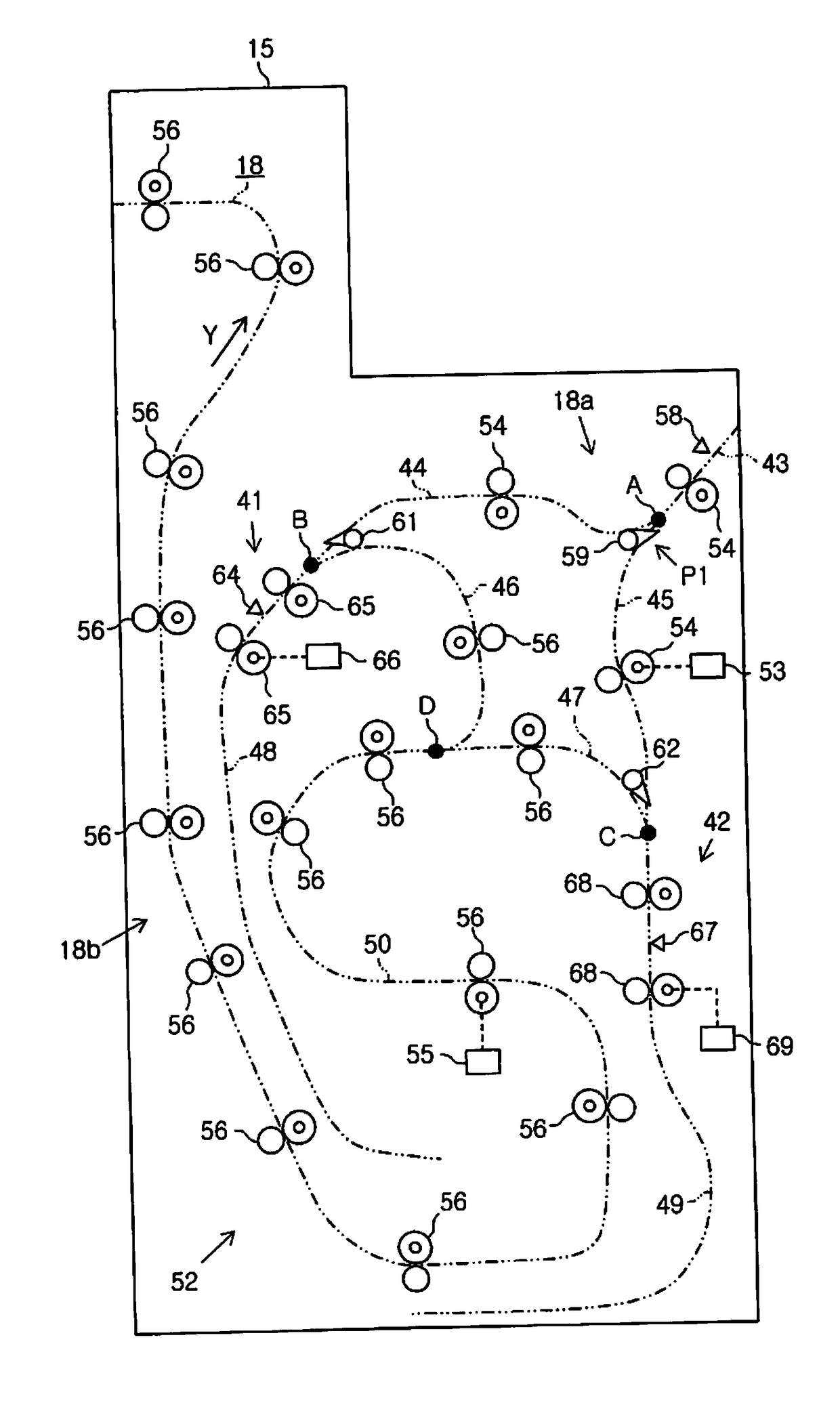
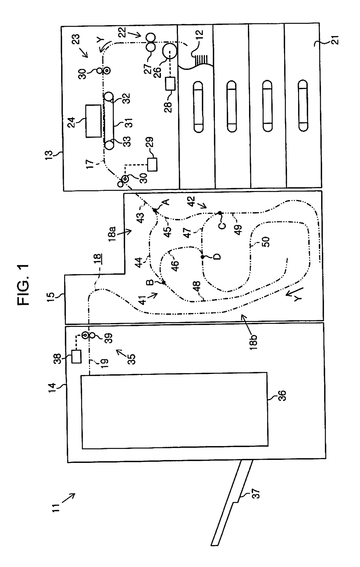
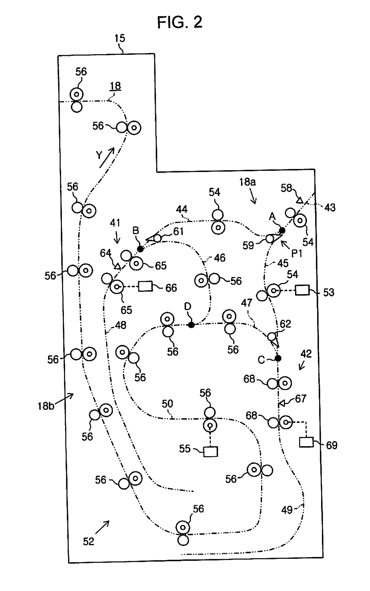
[0034]As described in FIG. 1, a print apparatus 11 includes a device main body 13 that is an example of a first device such as a printer performing printing on a medium 12 such as a sheet, a post-processing device 14 that is an example of a second device performing a process on the printed medium 12, and an intermediate device 15 that is an example of a third device positioned between the device main body 13 and the post-processing device 14.

[0035]An upstream side transport path 17 is provided in the device main body 13, and an intermediate transport path 18 is provided in the intermediate device 15. Furthermore, a downstream side transport path 19 is provided in the post-processing device 14. A transport path denoted by a two-dot chain in FIG. 1 is constituted by the upstream side transport path 17, the intermediate transport path 18, and the downstream side transport path 19 from...


PUM


Abstract

The present invention relates to a print system, such as an ink jet printer, which performs printing on a medium, such as a sheet that is transported.

Description

BACKGROUND[0001]1. Technical Field[0002]The present invention relates to a print system, such as an ink jet printer, which performs printing on a medium, such as a sheet that is transported.[0003]2. Related Art[0004]In the related art, as an example of a print apparatus, an image forming apparatus that records (prints) an image on a sheet (medium) that is transported is known. In addition, there is an image forming apparatus including a switchback mechanism (inversion unit) that inverts the sheet in the image forming apparatus (for example, JP-A-9-12198).[0005]That is, the switchback mechanism includes a roller, and a sheet fed from an upstream side transport path (first transport path) is sent and inverted on a downstream side transport path (second transport path) by rotating and counter-rotating the roller.[0006]In the image forming apparatus, two switchback mechanisms are provided; one roller is used as a roller that feeds the sheet to one switchback mechanism and another roller...

Claims


Application Information

Patent Timeline
IPC IPC(8): B41J2/005
CPCB41J2/0057B65H29/58B65H2801/03B41J13/0009B65H29/125B65H2301/33312
Inventor KODAMA, HIDETOSHIMUROMACHI, AKINORI
Owner SEIKO EPSON CORP
Why Eureka
Try Eureka