Method and device for message flooding in wireless communication system

a wireless communication and message technology, applied in data switching networks, power management, high-level techniques, etc., can solve problems such as resource shortfall, achieve the effect of preventing collision due to message retransmission, preventing unnecessary retransmission, and minimizing unnecessary retransmission

Active Publication Date: 2017-07-27
LG ELECTRONICS INC +1
View PDF6 Cites 7 Cited by
  • Summary
  • Abstract
  • Description
  • Claims
  • Application Information

AI Technical Summary

Benefits of technology

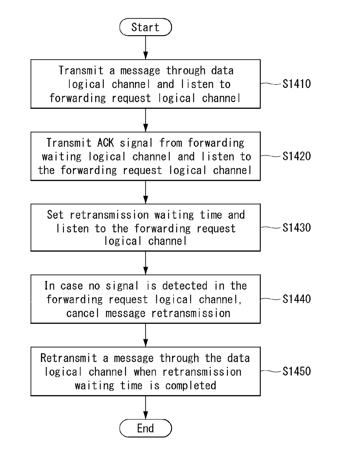
[0026]According to the present invention, since a message is retransmitted only when a node which has perceived message transmission explicitly requests retransmission of the message, unnecessary retransmission may be minimized, and collision due to message retransmission may be prevented.
[0027]Also, according to the present invention, in case a signal is not detected in a message retransmission request channel, retransmission may be cancelled, thereby preventing unnecessary retransmission beforehand and minimizing use of radio and energy resources of the whole network.
[0028]Also, according to the present invention, since nodes located close to the node which requests message retransmission retransmit the message, time required to complete message flooding may be minimized.
[0029]The advantageous effects that may be obtained from the present invention are not limited to the effects described above, but other advantageous effects not mentioned above may be clearly understood by those skilled in the art to which the present invention belongs.

Problems solved by technology

Today, the shortage of resources is caused due to an explosive increase of traffic, and more advanced mobile communication systems are required due to user's need for higher speed services.

Method used


Image

  • Method and device for message flooding in wireless communication system
  • Method and device for message flooding in wireless communication system
  • Method and device for message flooding in wireless communication system

Examples


Embodiment Construction

[0046]Hereafter, preferred embodiments of the present invention will be described in detail with reference to the accompanying drawings. A detailed description to be disclosed hereinbelow together with the accompanying drawing is to describe embodiments of the present invention and not to describe a unique embodiment for carrying out the present invention. The detailed description below includes details in order to provide a complete understanding. However, those skilled in the art know that the present invention can be carried out without the details.

[0047]In some cases, in order to prevent a concept of the present invention from being ambiguous, known structures and devices may be omitted or may be illustrated in a block diagram format based on core function of each structure and device.

[0048]In the specification, a base station means a terminal node of a network directly performing communication with a terminal. In the present document, specific operations described to be perform...


PUM


Abstract

The present disclosure relates to a method for message flooding in a wireless communication system, and is characterized in that it includes the steps of: broadcasting, by a transmission node, a flooding message to a surrounding node through a first common channel; checking, by a reception node, whether the first common channel has received the flooding message; transmitting, by the reception node, an ACK signal through a second common channel or a NACK signal through a third common channel, based on a result of the check; and determining, by the transmission node, whether the second common channel or the third common channel has detected a signal, to determine whether to re-transmit the flooding message.

Description

TECHNICAL FIELD[0001]The present invention relates to a wireless communication system and more particularly, a method for performing message flooding in a wireless communication system supporting device-to-device communication and an apparatus supporting the method.BACKGROUND ART[0002]Mobile communication systems have been developed to provide voice services while ensuring the activity of a user. However, the mobile communication systems have been expanded to their regions up to data services as well as voice. Today, the shortage of resources is caused due to an explosive increase of traffic, and more advanced mobile communication systems are required due to user's need for higher speed services.[0003]Requirements for a next-generation mobile communication system basically include the acceptance of explosive data traffic, a significant increase of a transfer rate per user, the acceptance of the number of significantly increased connection devices, very low end-to-end latency, and hi...

Claims


Application Information

Patent Timeline
Patent Type & Authority Applications(United States)
IPC IPC(8): H04L12/721H04L1/16H04W28/04H04W40/02
CPCH04L45/32H04W28/04H04L1/16H04W40/02H04L1/1685H04L1/1896H04L2001/0093H04W52/00Y02D30/70
Inventor KIM, HAKSEONGKANG, DAEHOBAHK, SAEWOONG
Owner LG ELECTRONICS INC
Why Eureka
Try Eureka