Eureka AIR delivers breakthrough ideas for toughest innovation challenges, trusted by R&D personnel around the world.

Elevator counterweight

Active Publication Date: 2017-08-03
KONE CORP
View PDF8 Cites 5 Cited by
  • Summary
  • Abstract
  • Description
  • Claims
  • Application Information

AI Technical Summary

Benefits of technology

The present invention provides a counterweight with sufficient weight that requires reduced space in an elevator shaft. The disclosed counterweight modules are cost-efficient to manufacture and can fill the entire vertical space between the side beams and crossbeams of the frame, increasing the efficiency of the counterweight without needing to increase the height of the frame. This is especially useful in elevator shafts where space is limited.

Problems solved by technology

The counterweight is placed in the elevator shaft and often space for it, both in vertical and horizontal directions, is limited.
This means that it is not possible to fill the entire vertical open space of the frame with full length modules.
As the frame is filled upwards from the lower crossbeam situated at the bottom of the frame, at a certain point it is no longer possible to angle the modules in order to fit them between the side beams, as the upper crossbeam at the top of the frame prevents sufficient angling of the modules.
The openings affect the structural integrity of the frame.
With this solution the mass distribution within the counterweight is not symmetric, which affects the balancing function of the counterweight.
These kinds of modules are expensive when made of steel, while constructing similar form-locking modules from concrete is very difficult, if not impossible.

Method used


Image

  • Elevator counterweight
  • Elevator counterweight
  • Elevator counterweight

Examples


Embodiment Construction

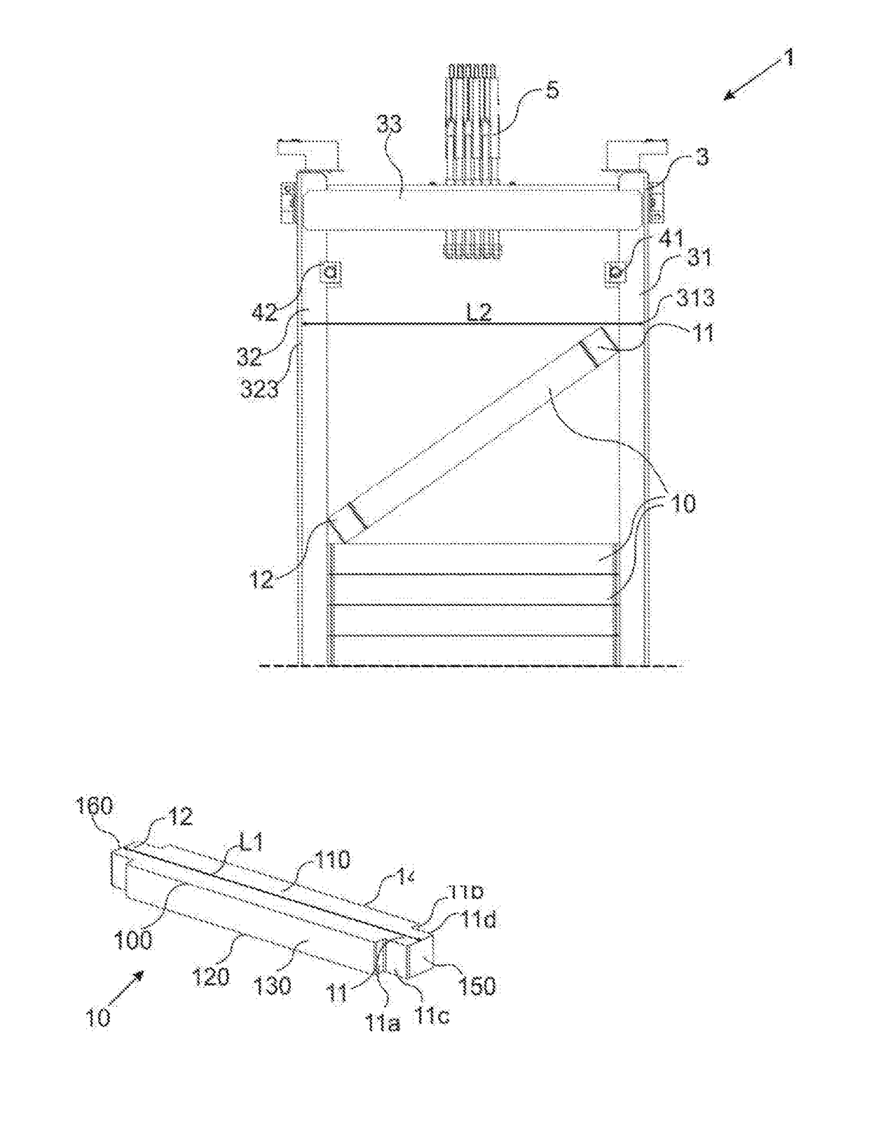
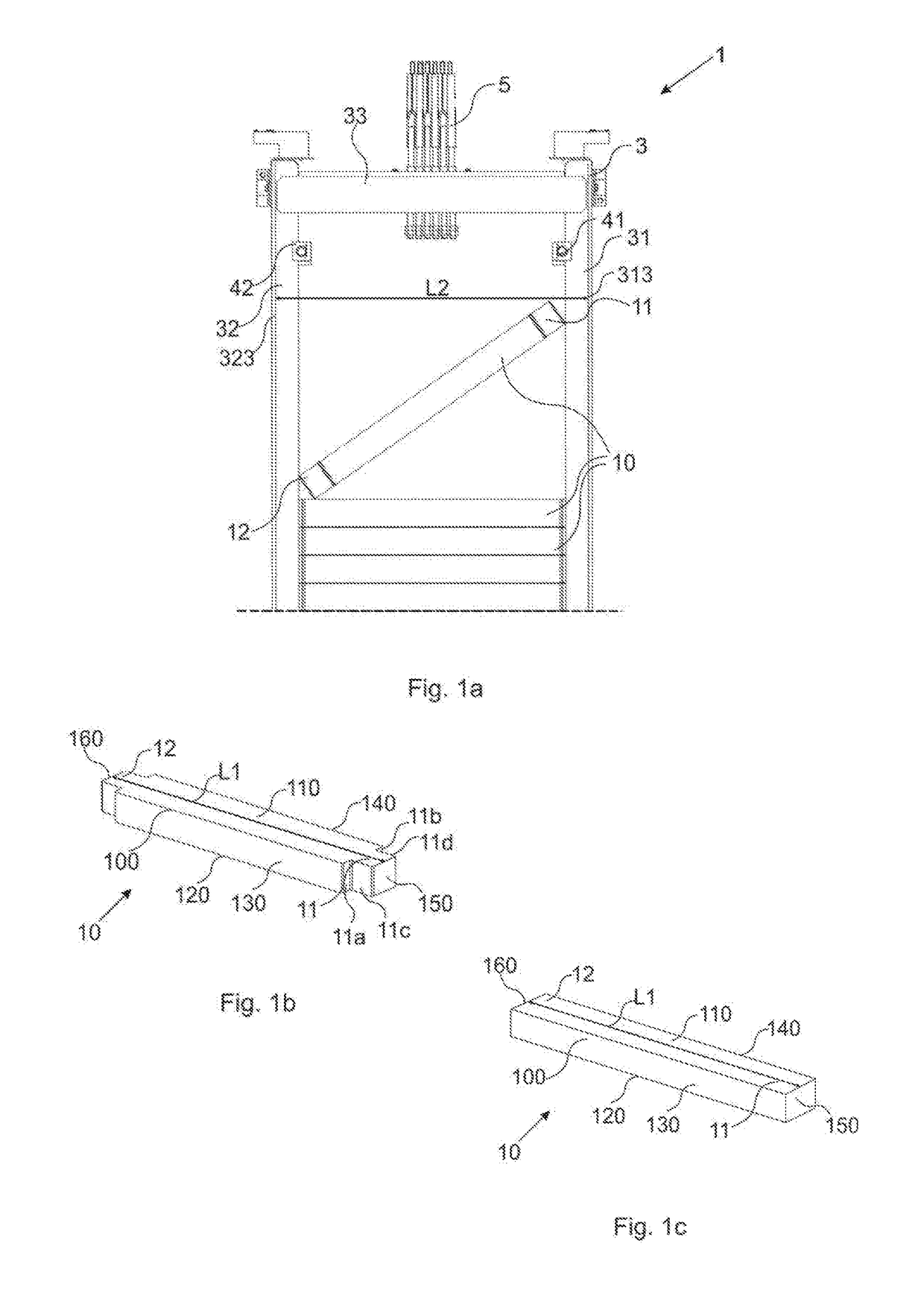
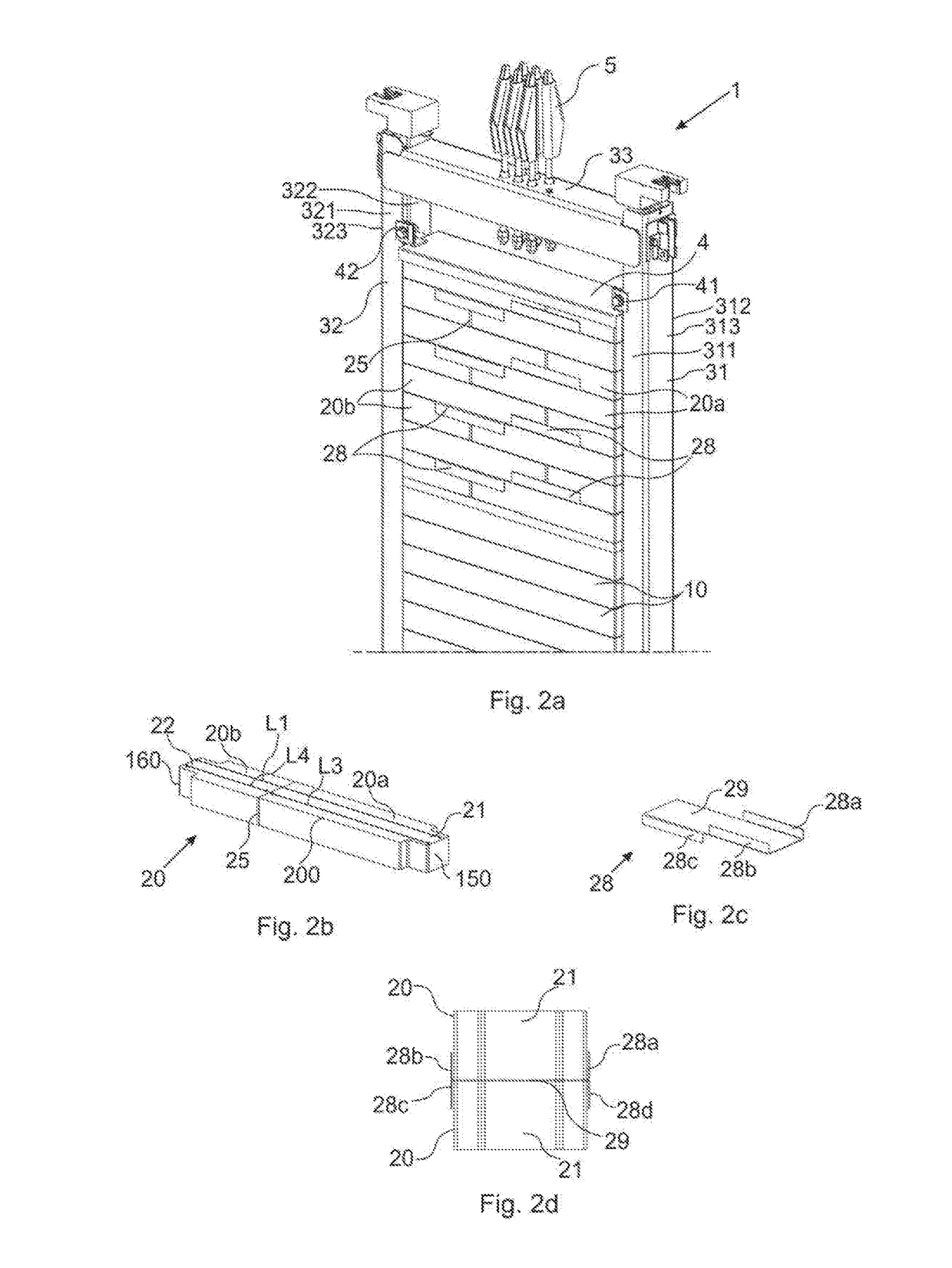
[0053]The counterweight 1 according to the present invention is presented in FIG. 1a, 2a, 3a, 4a and 5a. The counterweight comprises a frame 3 comprising a vertical first side beam 31, a vertical second side beam 32 and two horizontal crossbeams of which only the upper, top crossbeam 33 is shown throughout the accompanying figures. It is to be understood that the bottom crossbeam is arranged between the two side beams 31, 32 at the bottom of the frame 3, extending between the side beams 31, 32 horizontally and in alignment with the top crossbeam 33.

[0054]The frame 3 is filled from bottom crossbeam upwards with balancing modules 10, 20. Initially, first modules 10 are used so that the first of the first modules 10 is positioned directly on top of the bottom crossbeam, even though the bottom crossbeam and the bottom-most part of the counterweight 1 is not shown in the figures.

[0055]The counterweight 1 further comprises an arrangement 5 for attaching the hoisting cables used for moving...


PUM


Abstract

A counterweight module, a locking element, a counterweight and a method for assembling a counterweight are disclosed. The counterweight module includes a first part and a second part, between which a straight joint is arranged at right angle in relation to the longitudinal direction of the counterweight module. The counterweight locking element can be used to secure the counterweight modules into a counterweight frame. In the method, the counterweight is filled with balancing modules starting from the bottom of the frame.

Description

TECHNICAL FIELD[0001]The present disclosure relates to a counterweight module and to a locking element for counterweight modules, a counterweight, and a method for assembling a counterweight. Particularly, the counterweight module and the locking element, the counterweight and the method for assembling a counterweight are intended for elevators.BACKGROUND OF THE INVENTION[0002]In a traction elevator, a counterweight is used to balance the load of an elevator car, thus reducing power required for the vertical movement of the elevator car. The elevator car and the counterweight are attached to the opposing ends of a hoisting cable and they move reciprocally in the elevator shaft. The movement of the counterweight is usually directed by at least one guide rail, typically by two that are located on two opposing sides of the counterweight.[0003]The counterweight is formed of a metal frame, often including two vertical side beams and two horizontal crossbeams. The weight of the counterwei...

Claims


Application Information

Patent Timeline
IPC IPC(8): B66B17/12
CPCB66B17/12B66B7/00
Inventor MIKKONEN, JANNERASANEN, MATTIAULANKO, ESKOMUSTALAHTI, JORMAMANNINEN, VEIJOHEIKKINEN, JARIKELA, JARMOKORVENRANTA, SAKARIBARNEMAN, HAKAN
Owner KONE CORP
Why Eureka
Eureka Blog
Learn More