Work vehicle

a technology for working vehicles and parts, applied in the field of work vehicles, can solve the problems of inability to improve the workability of mounting dpf or shockproof, the size of the engine, and the inability to simplify the support structure of the dpf, so as to prevent the upper section of the engine from being heated, eliminate the difficulty of component mounting and maintenance, and eliminate the difficulty of maintenance work

Active Publication Date: 2017-08-03
YANMAR POWER TECHNOLOGY CO LTD
View PDF2 Cites 20 Cited by
  • Summary
  • Abstract
  • Description
  • Claims
  • Application Information

AI Technical Summary

Benefits of technology

[0006]Increase in the size of the engine not only requires a design change in the work vehicle due to an insufficient engine mounting space in the work vehicle, but also deteriorates ease of maintenance depending on the mounting state of the engine. Furthermore, increase in the size of the engine deteriorates the flow of cooling air in the engine compartment so that cooling effect is reduced. The heat retention in the engine compartment may possibly cause a failure not only in the electronic components, but also in the engine due to heating.
[0025]With the embodiment of the invention of the present application, the pressure drop in the offset region between the cooling fan and the radiator is reduced, so that the velocity distribution of the cool air that flows within the fan shroud is equalized. As a result, a pressure differential within the fan shroud is inhibited, so that backflow of the cool air within the radiator is prevented, and thus the cooling efficiency of the radiator is increased. Furthermore, since the pressure drop in the offset region between the cooling fan and the radiator is reduced, introduction of the cool air is facilitated and thus the load imposed on the cooling fan is reduced.

Problems solved by technology

Since the support structure of the DPF, however, is not easily simplified, the workability in mounting the DPF or shock proof cannot be improved.
Increase in the size of the engine due to mounting of the DPF increases influence caused by vibration of the engine having different vibration systems, and breakage or failure may possibly occur in a component that needs to be coupled to both the traveling body and the engine (for example, an exhaust pipe).
Increase in the size of the engine not only requires a design change in the work vehicle due to an insufficient engine mounting space in the work vehicle, but also deteriorates ease of maintenance depending on the mounting state of the engine.
Furthermore, increase in the size of the engine deteriorates the flow of cooling air in the engine compartment so that cooling effect is reduced.
The heat retention in the engine compartment may possibly cause a failure not only in the electronic components, but also in the engine due to heating.

Method used


Image

  • Work vehicle
  • Work vehicle
  • Work vehicle

Examples


Embodiment Construction

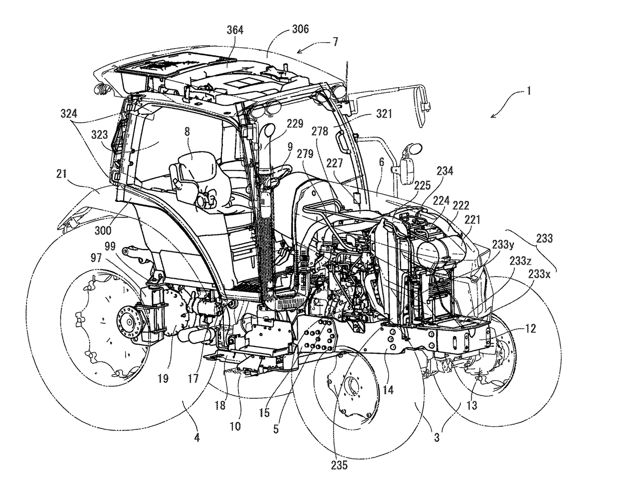
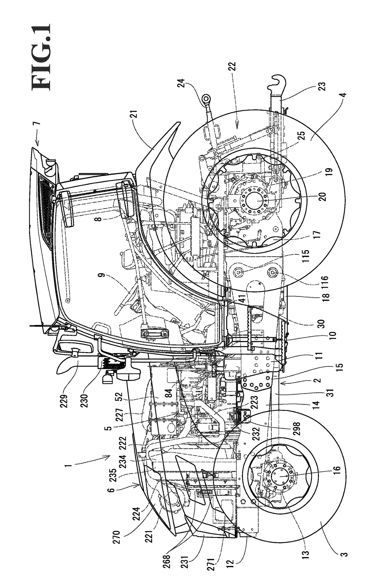
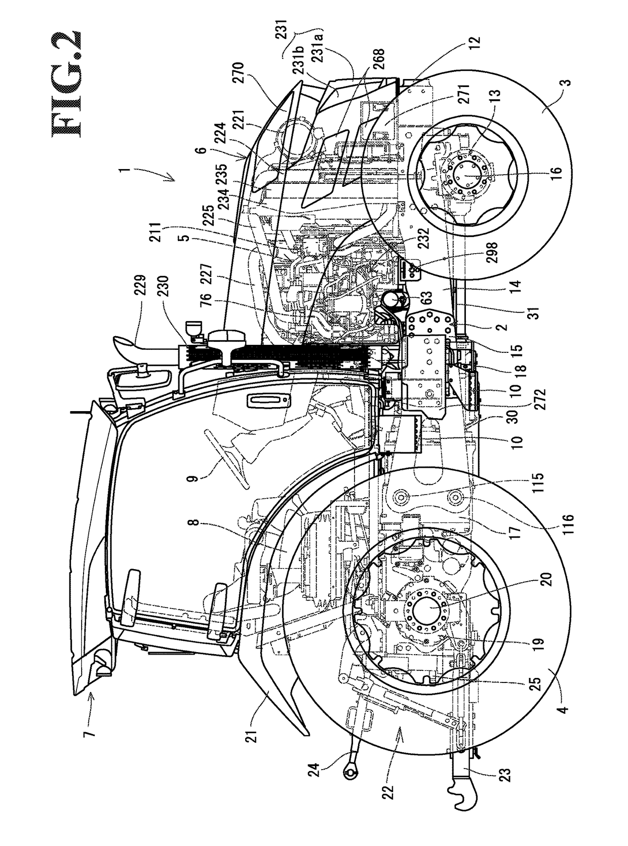
[0064]Hereinafter, an embodiment of the present invention will be described with reference to the drawings. First, a configuration of a tractor 1 according to the embodiment will be described with reference to FIGS. 1 to 10. The tractor 1 is a work vehicle. A traveling body 2 of the tractor 1 according to this embodiment is supported by traveling sections, which are a pair of left and right front wheels 3 and a pair of left and right rear wheels 4 in this embodiment. The rear wheels 4 and the front wheels 3 are driven by a power source mounted on the front section of the traveling body 2. The power source is the common rail diesel engine 5 (hereinafter, simply referred to as the engine) in this embodiment. The tractor 1 travels forward and backward by driving the rear wheels 4 and the front wheels 3. The engine 5 is covered with a hood 6. A cabin 7 is provided on the upper surface of the traveling body 2. An operator's seat 8 and a steering wheel (round steering wheel) 9 are located...


PUM


Abstract

A work vehicle includes a hood, an engine, a radiator, an air cleaner, and a condenser. The hood covers an engine compartment located on a front portion of a traveling body. The engine is a drive source. The radiator supplies a coolant to the engine. The air cleaner takes in outside air and supplies the air to the engine. The condenser cools a refrigerant. In front of the radiator, the air cleaner and the condenser are disposed one above the other. The condenser is withdrawable in the left and right direction.

Description

CROSS-REFERENCE TO RELATED APPLICATIONS[0001]The present application is a continuation application of International Application No. PCT / JP2015 / 078380, filed Oct. 6, 2015, which claims priority to Japanese Patent Application No. 2014-211350, filed Oct. 16, 2014 and Japanese Patent Application No. 2015-079709, filed Apr. 9, 2015. The contents of these applications are incorporated herein by reference in their entirety.BACKGROUND OF THE INVENTION[0002]The invention of the present application relates to work vehicles.[0003]As higher-level emission regulations have been applied to diesel engines (hereinafter, simply referred to as engines), agricultural vehicles and construction and engineering machines that include an engine are required to include an exhaust gas purification device that removes air pollutants in exhaust gas. Diesel particulate filters (hereinafter, referred to as the DPF) that collect, for example, particulate matter in exhaust gas (for example, refer to Japanese Unexa...

Claims


Application Information

Patent Timeline
Patent Type & Authority Applications(United States)
IPC IPC(8): F01P1/02B60K13/02B62D25/10B62D21/18B60K13/04F01N3/021B62D49/06F02B29/04F01P11/08F01P11/12F01P11/02F01P11/10B60K11/04B62D25/04
CPCF01P1/02B60K11/04B60K13/02B62D25/10B62D21/18B60K13/04F01N3/021B62D49/06F02B29/0406F01P11/08F01P11/12F01P11/0295F01P11/10B62D25/04B60Y2200/221B62D21/186E02F9/0808E02F9/0866F01N13/08F01N13/1805F01N2340/04F01N2590/08F01P5/06F01P7/16F01P2060/04F01P2060/10F01P2060/14F02B29/0431F02M35/048F02M35/164Y02T10/12B60Y2200/415E02F9/00
Inventor KUROKAWA, YOSHIAKIKAWAKAMI, KOJI
Owner YANMAR POWER TECHNOLOGY CO LTD
Why Eureka
Try Eureka