MODES OF THE INVENTION
[0034]Hereinafter, exemplary embodiments of the present invention will be described in detail with reference to the accompanying drawings. These embodiments are provided so that the technical idea of the present invention may be completely delivered to those of ordinary skill in the art. The present invention is not limited to the embodiments set forth herein and can be implemented in various forms. In the drawings, elements that are not related to describing these embodiments are not illustrated to clarify the present invention, and the sizes of elements may be exaggerated to help understanding of the invention.
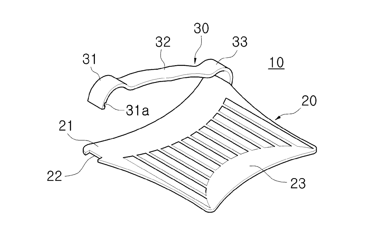
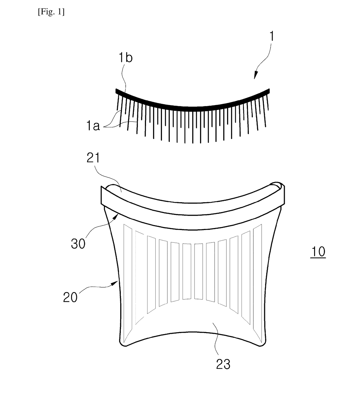
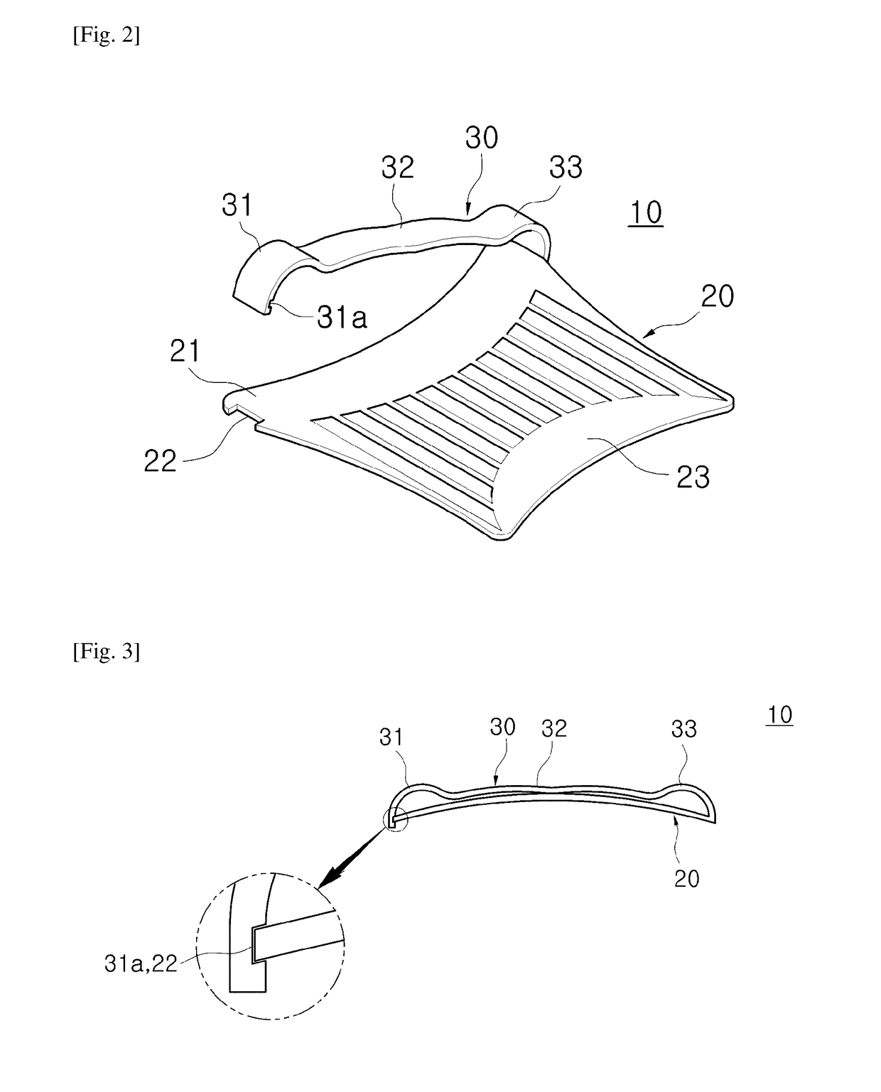
[0035]An artificial eyelash applicator 10 according to one embodiment of the present invention is provided to store artificial eyelashes 1 such that the artificial eyelashes 1 may be directly attached to an eyelid or is provided to be used to attach the artificial eyelashes 1 to an eyelid. Here, similar to general artificial eyelashes, the artificial eyelashes 1 may include a plurality of eyelash strands 1a, and a joining portion 1b connecting one-side ends of the plurality of eyelash strands 1a to each other. The plurality of eyelash strands 1a may be prepared using artificial fur. FIG. 1 illustrates the structure of the artificial eyelashes 1 which are general artificial eyelashes.
[0036]As illustrated in FIGS. 1 to 6, the artificial eyelash applicator 10 includes a support plate 20 configured to support the plurality of eyelash strands 1a of the artificial eyelashes 1, and a holding pin 30 configured to push and hold the plurality of eyelash strands 1a on the support plate 20 in a lengthwise direction of the joining portion 1b.
[0037]The support plate 20 may be provided in the form of a thin plate having a roughly quadrangle shape such that the plurality of eyelash strands 1a of the artificial eyelashes 1 are placed and supported on an upper surface of one end thereof.
[0038]One end portion of a front side of the support plate 20 in which the plurality of eyelash strands 1a are supported on an upper surface thereof may form a support portion 21.
[0039]A front surface of the support portion 21 may be inwardly concave toward an inner side of the support plate 20 to correspond to the shape of an eyelid which is outwardly convex.
[0040]The joining portion 1b of the artificial eyelashes 1 with the plurality of eyelash strands 1a supported by the upper surface of the support portion 21 is positioned in front of the support plate 20.
[0041]One end of the holding pin 30 may be integrally coupled to one side of the support portion 21 of the support plate 20, and another end thereof may be provided to be engaged with another side of the support portion 21 of the support plate 20 to be attachable to or detachable from the other side of the support portion 21. To this end, an engagement groove 31a may be formed in the other end of the holding pin 30, and an engagement portion 22 may be provided in the other side of the support portion 21 of the support plate 20 corresponding to the engagement groove 31a such that it is fixed by being engaged with the engagement groove 31a.
[0042]Furthermore, a compressing portion 32 may be provided between the one end and the other end of the holding pin 30, such when the engagement groove 31a is fixed by being caught by the engagement portion 22, the compressing portion 32 is adhered onto the support plate 20 to push and hold the plurality of eyelash strands 1a on the upper surface of the support portion 21 of the support plate 20 to be adhered to the upper surface of the support portion 21.
[0043]Thus, the artificial eyelashes 1 supported on the support portion 21 of the support plate 20 may be safely held by the artificial eyelash applicator 10 in a state in which the plurality of eyelash strands 1a are elastically compressed between the compressing portion 32 of the holding pin 30 and the upper surface of the support portion 21.
[0044]When the plurality of eyelash strands 1a of the artificial eyelashes 1 are grasped between the support plate 20 and the holding pin 30, the support plate 20 and the holding pin 30 may be each formed of a transparent material or a semi-transparent material so that a user may easily check whether the plurality of eyelash strands 1a are grasped by an appropriate length with the user's eyes.
[0045]An engagement structure of the engagement portion 22 and the engagement groove 31a may be immediately released when the support plate 20 is elastically deformed. Thus, the artificial eyelashes 1 grasped between the support plate 20 and the holding pin 30 may be easily separated from the artificial eyelash applicator 10 as a user elastically deforms the support plate 20.
[0046]The support plate 20 and the holding pin 30 may be integrally formed with each other using polypropylene (PP) to have a flexible property, so that the support plate 20 may be smoothly elastically deformed and the compressing portion 32 of the holding pin 30 may be easily elastically adhered to the support plate 20.
[0047]When it is considered that the holding pin 30 is positioned at an upper portion of the support portion 21 which is one end of the support plate 20, the artificial eyelash applicator 10 may be provided such that engagement of the engagement portion 22 and the engagement groove 31a is released in a state in which the support plate 20 is elastically deformed to be convex upwardly toward the holding pin 30.
[0048]At least the support portion 21 which is one end of the support plate 20 corresponding to the position of the holding pin 30 may be curved to be convex upwardly toward the holding pin 30 when external force is not applied thereto, so that the support plate 20 may be smoothly elastically deformed to release the engagement of the engagement portion 22 and the engagement groove 31a.
[0049]In the present embodiment, the support plate 20 is curved to be convex upwardly toward the holding pin 30 from one end to another end thereof between opposite sides of the support plate 20 when external force is not applied thereto.
[0050]Thus, the artificial eyelashes 1 may be easily separated from the artificial eyelash applicator 10 having the above structure when a user simply puckers an end portion of the support plate 20 opposite to the holding pin 30 to be more convex upwardly in a state in which the artificial eyelashes 1 are held.
[0051]A curvature of the support portion 21 may be the same as an average curvature of eyelids. The artificial eyelashes 1 supported by the support portion 21 are naturally adjusted to match the shape of a user's eyelid due to the structure of the support plate 20 in which the front surface of the support portion 21 is concave toward the inner side of the support plate 20 to correspond to the shape of an eyelid which is convex outwardly in a front direction and the support portion 21 is curved to be convex upwardly to match the average curvature of eyelids. Thus, when the artificial eyelashes 1 supported by the support portion 21 are placed on an eyelid, the artificial eyelashes 1 may be directly and exactly attached to the eyelid in a state in which the shape of the artificial eyelashes 1 matches the shape of the eyelid.
[0052]A user may easily inwardly pucker the end portion of the support plate 20 opposite to the holding pin 30 while grasping opposite sides of the end portion to not interfere with separation of the holding pin 30 during separating the artificial eyelashes 1 grasped by the artificial eyelash applicator 10 from the artificial eyelash applicator 10. The end portion of the support plate 20 opposite the support portion 21 may form a manipulation portion 23. In this case, in the support plate 20, a width of the manipulation portion 23 which is grasped with a user's hand may be less than that of the support portion 21 which is substantially the same in length as the artificial eyelashes 1 so that the user may easily pucker the manipulation portion 23 inwardly by grasping opposite sides of the manipulation portion 23.
[0053]In the holding pin 30, one side of the compressing portion 32 having the engagement groove 31a forms a holding portion 31, and another side thereof forms a coupling portion 33 integrally coupled to the support plate 20. The engagement groove 31a may be provided in an inner surface of the holding portion 31 extending to cover one side of the support portion 21.
[0054]The compressing portion 32 may be maintained in a flat form almost similar to a straight line when external force is not applied thereto, so that it may be elastically adhered to the support portion 21 of the support plate 20 in a state in which the engagement portion 22 is fixed by being caught into the engagement groove 31a. The holding portion 31 and the coupling portion 33 at opposite sides of the compressing portion 32 may be spaced apart from each other toward the upper portion of the support portion 21 in a state in which the compressing portion 32 is adhered to the support portion 21.
[0055]As illustrated in FIGS. 2 and 4, when the engagement of the engagement groove 31a and the engagement portion 22 is released, the coupling portion 33 makes the holding pin 30 tilt upwardly toward a side opposite to the coupling portion 33 so that the support plate 20 and the holding pin 30 may be rapidly separated from each other to be spaced apart from each other. Thus, the gasped artificial eyelashes 1 may be more immediately separated from the artificial eyelash applicator 10.
[0056]In the structure of the artificial eyelash applicator 10 described above, the positions of the engagement groove 31a and the engagement portion 22 may be switched to each other. The engagement structure of the holding pin 30 and the support plate 20 may be replaced with various engagement structures such as a snap fastener or a hook including female and male parts, provided that the holding pin 30 and the support plate 20 are disengaged from each other as the support plate 20 is elastically deformed.
[0057]Next, a process of attaching the artificial eyelashes 1 using the artificial eyelash applicator 10 having the above structure will be described below.
[0058]As illustrated in FIGS. 5 and 6, the artificial eyelash applicator 10 with the artificial eyelashes 1 grasped between the support plate 20 and the holding pin 30 may be accommodated in a portable storage box (not shown) or the like in ordinary times.
[0059]In this state, an adhesive may be applied to the joining portion 1b of the artificial eyelashes 1 so that the artificial eyelashes 1 may be attached to an eyelid. The adhesive may be applied to the joining portion 1b before the artificial eyelashes 1 is held on the artificial eyelash applicator 10.
[0060]One or more artificial eyelash applicators 10 in the above state may be accommodated in a storage box (not shown) according to the size of the storage box.
[0061]In order to wear the artificial eyelashes 1, a user may pull out the artificial eyelash applicator 10 from the storage box and place it around her eye while grasping the manipulation portion 23. In this case, the user may grasp opposite sides of the manipulation portion 23 with her thumb f1 and index finger f2 without applying force thereto so that the manipulation portion 23 may not be puckered.
[0062]Then, as illustrated in FIG. 7, the user places the artificial eyelash applicator 10 around the user's eye and adheres the joining portion 1b of the artificial eyelashes 1 to an eyelid 2 adjacent to the user's lash line. Thus, the joining portion 1b is attached to the eyelid 2 due to the adhesive strength of the adhesive applied to the joining portion 1b.
[0063]In this state, as illustrated in FIG. 8, the user inwardly puckers the opposite sides of the manipulation portion 23 by applying force thereto with her thumb f1 and index finger f2 such that the support plate 20 becomes more convex upwardly. Thus, as the support portion 21 is elastically deformed to be convex, the engagement of the engagement groove 31a and the engagement portion 22 is released and thus the artificial eyelashes 1 are in a state to be separated from the support plate 20 and the holding pin 30. Thus, in this state, when the artificial eyelash applicator 10 is moved from the user's face in the forward direction, the artificial eyelash applicator 10 is removed from the artificial eyelashes 1, thereby making the artificial eyelashes 1 safely attached to the user's eyelid 2.
[0064]In order to stop wearing of the artificial eyelashes 1 in this state, the user may remove the artificial eyelashes 1 from the eyelid 2, place the artificial eyelashes 1 between the support plate 20 and the holding pin 30 to be elastically grasped therebetween such that the artificial eyelashes 1 may be immediately used when necessary, and then store the artificial eyelash applicator 10 in this state again in the storage box.
[0065]As described above, in the artificial eyelash applicator 10 according to the present embodiment, the artificial eyelashes 1 may be elastically pushed and held using the holding pin 30 while being stably supported on the support plate 20. The artificial eyelashes 1 in this state may be easily separated from the artificial eyelash applicator 10 by simply puckering the support plate 20 to be elastically deformed.
[0066]Accordingly, with use of the artificial eyelash applicator 10 according to the present embodiment, the artificial eyelashes 1 may be easily stored in a state in which they may be immediately fixed on the eyelid 2 without a separate adhesive.
[0067]Furthermore, the grasped artificial eyelashes 1 may be easily separated from the artificial eyelash applicator 10 according to the present embodiment by simply puckering the support plate 20 according to a one-touch method. Thus, a possibility that the grasped artificial eyelashes 1 will be separated from the eyelid 2 during attaching the grasped artificial eyelashes 1 to the eyelid 2 may be effectively decreased.
[0068]In the present disclosure, exemplary embodiments of the present invention have been illustrated and described. However, the present invention is not limited thereto, and may be embodied in many different forms by those of ordinary skill in the art without departing from the scope of the technical idea of the invention described in the following claims.