Method for operating a controllable shock absorber for motor vehicles

a technology of controllable shock absorbers and motor vehicles, which is applied in the direction of shock absorbers, vibration dampers, springs/dampers, etc., can solve problems such as unsatisfactory side effects, and achieve the effect of reducing the number of required parts

Active Publication Date: 2017-08-17
THYSSENKRUPP BILSTEIN +1
View PDF10 Cites 7 Cited by
  • Summary
  • Abstract
  • Description
  • Claims
  • Application Information

AI Technical Summary

Benefits of technology

[0015]It is preferred here that the outflow valve adjoins the first and the second outflow path on the outflow side. The outflow valve it

Problems solved by technology

This results, however, in an interaction between the function of the pilot control valve and the

Method used


Image

  • Method for operating a controllable shock absorber for motor vehicles
  • Method for operating a controllable shock absorber for motor vehicles
  • Method for operating a controllable shock absorber for motor vehicles

Examples


Embodiment Construction

[0019]Further measures which develop the invention will be shown in greater detail in the following text together with the description of preferred exemplary embodiments of the invention, using the figures, in which:

[0020]FIG. 1 shows a conventional shock absorber with a valve assembly in cross section,

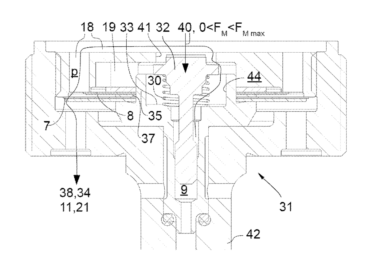
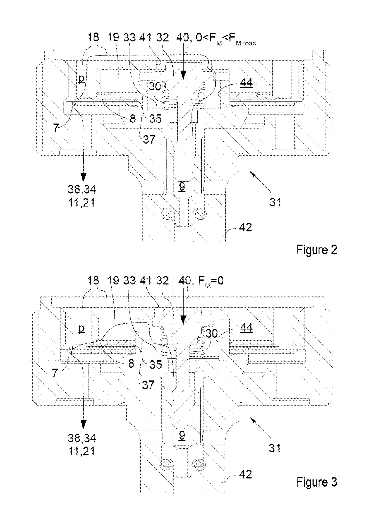
[0021]FIG. 2 shows the cross section through a pilot control valve of a shock absorber according to the invention in a first operating state,

[0022]FIG. 3 shows the cross section through a pilot control valve of a shock absorber according to the invention in a second operating state, and

[0023]FIG. 4 shows the damping force profile of a conventional shock absorber.

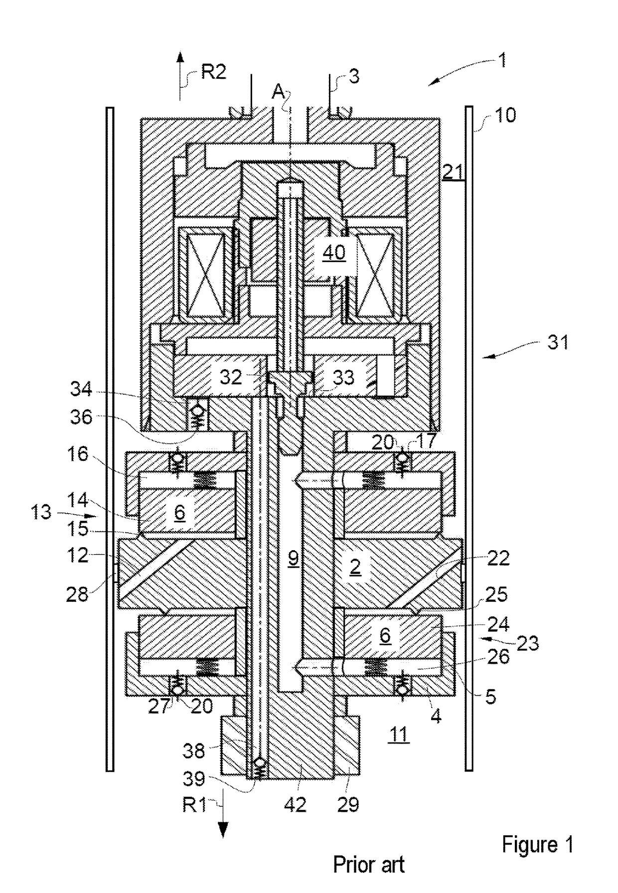
[0024]FIG. 1 shows the section of a conventional shock absorber 1.

[0025]The shock absorber 1 comprises a cylinder tube 10, in which a piston 2 is held such that it can be displaced along a cylinder tube axis A. The piston 2 has an annular seal or a piston band 28 on its outer circumference, with the result that the piston 2 di...


PUM


Abstract

A method for operating a controllable shock absorber may involve damping movement of a valve body by loading the valve body with a back pressure on an outflow side. Further, the controllable shock absorber may include a cylinder tube, a piston within the cylinder tube that divides the cylinder tube into two working spaces and includes a couple fluid leadthroughs connecting the working spaces, and first and second valve assemblies for damping piston movement in first and second actuating directions that are disposed on the leadthroughs. Each valve assembly may have a pilot control chamber and a valve plate that is either seated on or spaced apart from a valve seat in closed and open valve positions. Each valve plate can be prestressed closed by pressure loading the pilot control chamber. The pressures of the pilot control chambers can be set by a pilot control valve that comprises a movable valve body. As a result, an outflow cross section between the pilot control chambers and the working spaces can be set. The valve body may be loaded on an outflow side with a back pressure, as a result of which movement of the valve body is damped.”

Description

[0001]The present invention relates to a method for operating a controllable shock absorber in accordance with the preamble of claim 1 and to a corresponding shock absorber in accordance with the preamble of claim 2.PRIOR ART[0002]A corresponding shock absorber is known from DE 44 41 047 C1. Pressure-dependent damping valves for an exchange of fluid in the rebound and compression stage between two working spaces are provided on a piston which is guided axially within a cylinder tube. A pilot control means acts in such a way that a controllable pressure is built up in pilot control chambers. The pilot control pressure loads the valve plates of the damping valves into their closed position. By way of a bypass duct system, fluid is guided out of the working spaces into the pilot control chambers and the pressure is thus increased there. The pilot control pressure is regulated with the aid of a pilot control valve which can be set externally and is arranged in the bypass duct system. An...

Claims


Application Information

Patent Timeline
IPC IPC(8): F16F9/46F16F9/34F16F9/348
CPCF16F9/465F16F9/3481F16F9/3405F16F9/3484
Inventor HAMERS, WOLFGANGLENZ, TOBIAS
Owner THYSSENKRUPP BILSTEIN
Why Eureka
Try Eureka