Central Loose Tube Optical-Fiber Cable
a technology of optical fiber and loose tube, applied in the direction of optics, fibre mechanical structures, instruments, etc., can solve the problems of optical fiber attenuation, loose tube optical fiber cables are vulnerable to excessive temperature-induced shrinkage, and rigid strength members are not practicable for cable deployments requiring flexibility and no preferential bending axis, etc., to achieve the effect of limiting shrinkage force(s)
- Summary
- Abstract
- Description
- Claims
- Application Information
AI Technical Summary
Benefits of technology
Problems solved by technology
Method used
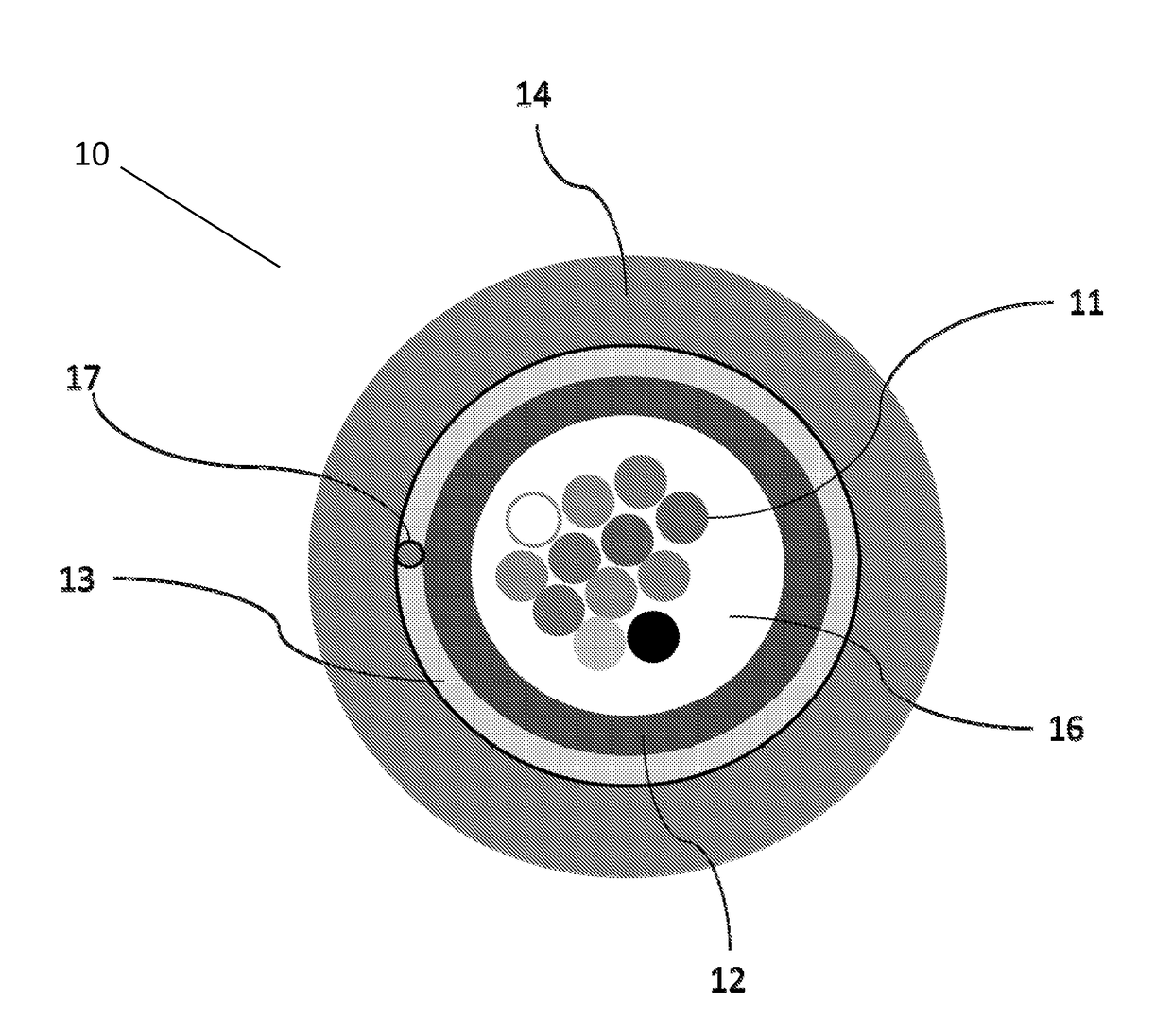
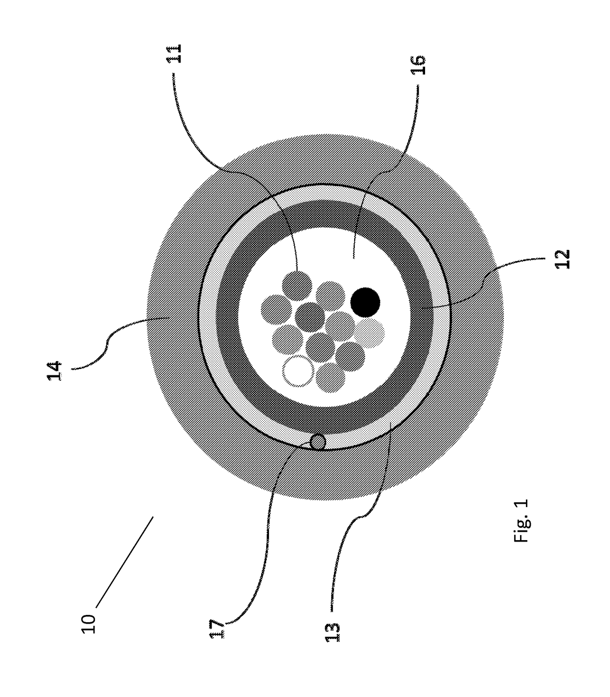
Image

Examples
example 1
[0021]
tex lbf per texload atload atpertotal 1% 0.6% 1% yarnsnumberyarntexelongationelongationelongationfiberglass767547250.05153256aramid31614830.164777totals5208200333
[0022]In Example 1 (above), as between the fiberglass strength yarns and aramid strength yarns, the fiberglass strength yarns provide about 91 percent of the combined strength-yarn tensile strength.
example 2
[0023]
tex lbf per texload atload atper total 1% 0.6% 1% yarnsnumberyarntexelongationelongationelongationfiberglass467527000.0588146aramid816112880.16124206totals3988211352
[0024]In Example 2 (above), as between the fiberglass strength yarns and aramid strength yarns, the fiberglass strength yarns provide about 68 percent of the combined strength-yarn tensile strength.
example 3
[0025]
tex lbf per texload atload atper total 1% 0.6% 1% yarnsnumberyarntexelongationelongationelongationfiberglass367520250.0566110aramid916114490.16139232totals3474205341
[0026]In Example 3 (above), as between the fiberglass strength yarns and aramid strength yarns, the fiberglass strength yarns provide about 58 percent of the combined strength-yarn tensile strength.
[0027]Excess fiber length (EFL) typically varies over the optical-fiber cable's operational temperatures (e.g., −40° C. to 40° C.). Including strength yarns helps to control excess fiber length (EFL), which is related to the interaction of contraction forces and core rigidity, not only during the buffering process but also at extreme temperatures (e.g., −20° C. or less). As noted, at 23° C., the present optical-fiber cable typically achieves excess fiber length (EFL) of less than 0.3 percent, more typically 0.2 percent (e.g., 0.1 percent or less).
[0028]Moreover, post-extrusion shrinkage (PES) often contributes to attenua...
PUM
 Abstract
Description
Claims
Application Information
 - R&D Engineer
- R&D Manager
- IP Professional
- Industry Leading Data Capabilities
- Powerful AI technology
- Patent DNA Extraction
Browse by: Latest US Patents, China's latest patents, Technical Efficacy Thesaurus, Application Domain, Technology Topic.
© 2024 PatSnap. All rights reserved.Legal|Privacy policy|Modern Slavery Act Transparency Statement|Sitemap