Self-forming polymer waveguide and waveguide material with reduced shrinkage

Active Publication Date: 2007-03-08
GENERAL ELECTRIC CO
View PDF11 Cites 15 Cited by
  • Summary
  • Abstract
  • Description
  • Claims
  • Application Information

AI Technical Summary

Benefits of technology

[0008] In accordance with one aspect of the invention, a cured composition for an optical device is provided. The cured composition comprises structural units derived from a first photocurable material, a second photocurable

Problems solved by technology

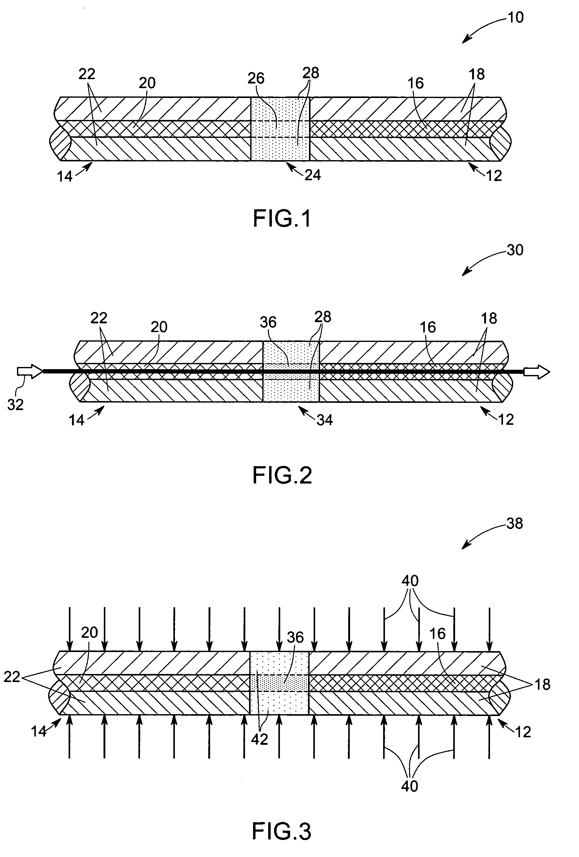
During the formation of conventional waveguide structures, severe shrinkage can occur.
This can result in movement of the original waveguide away from the end of the optical fiber that formed the waveguide, thus increasing the scatter loss of light traveling through the bulk material due to poor coupling between the fiber tip and the formed waveguide.
Techniques proposed to reduce shrinkage problem in the device may require complicated optimization and costly design processes.
In certain types of structures and particular applications, the shrinkage problem becomes particularly severe.
Even relatively modest shrinkage can lead to severe mismatches in alignment of light transmitting pathways between the linked fibers, resulting in unacceptable loss of coupling and consequently poor efficiency.

Method used


Image

  • Self-forming polymer waveguide and waveguide material with reduced shrinkage
  • Self-forming polymer waveguide and waveguide material with reduced shrinkage
  • Self-forming polymer waveguide and waveguide material with reduced shrinkage

Examples


example 1

[0054] The following materials were blended together with mixing, followed by filtration through a 0.5 microns nominal sized filter and degassed: [0055] 10 grams ERL4221®; [0056] 20 grams ERL4299®; [0057] 3.5 grams KFLEX® 188; [0058] 15 grams EBECRYL3700®; [0059] 0.15 grams SILWET7604®; [0060] 0.8 grams CYRACURE UVI-6992®; [0061] 0.05 grams IRGACURE 819®; [0062] 0.08 grams IRGACURE 184®.

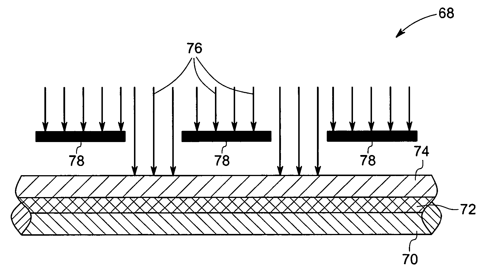
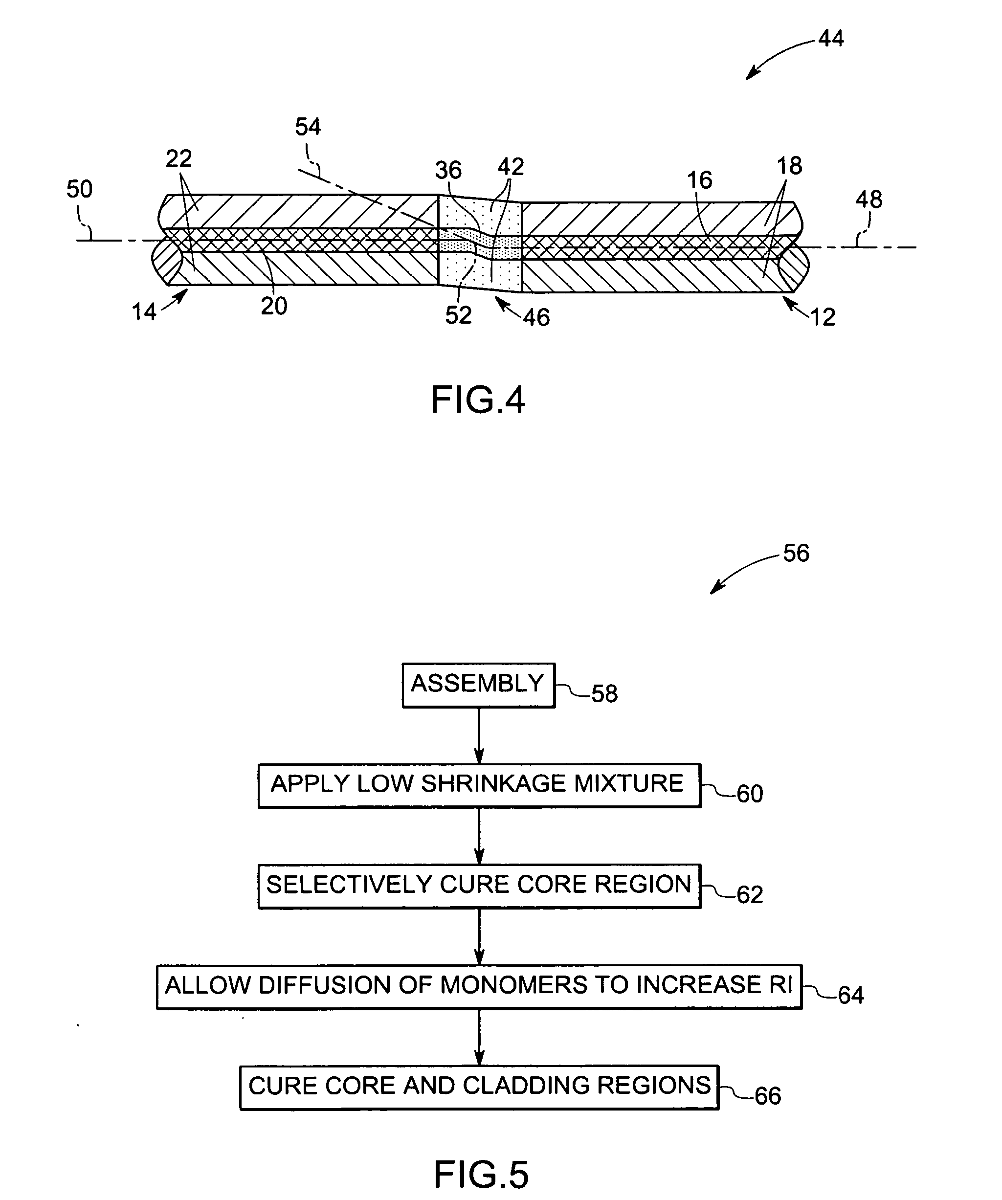
[0063] Subsequently, the mixture was exposed to radiation between 400 nanometers to 450 nanometers. Subsequently, the mixture was further exposed to a radiation from 365 nanometers. The measurement of shrinkage after curing a sample as described above indicated less than 1% shrinkage.

example 2

[0064] The following materials were blended together with mixing, followed by filtration through a 0.5 microns nominal sized filter and degassed: [0065] 10 grams ERL4221®; [0066] 20 grams ERL4299®; [0067] 15 grams SR-101®; [0068] 0.15 grams SILWET7604®; [0069] 0.8 grams CYRACURE UVI-6992®; [0070] 0.05 grams IRGACURE 819®; [0071] 0.08 grams IRGACURE 184®. [0072] 0.5 gr CXC-1612

[0073] The mixture was coated onto a silicon wafer substrate to form a homogeneous, thin film of about 25 microns thick. A portion of the film was exposed to a first radiation having a wavelength in the range of from about 400 nanometers to about 450 nanometers. Subsequently, the already exposed portion of the film was exposed to a second radiation having a wavelength of 365 nanometers. The film was then baked ramped form 80° C. to 190° C. over an hour and held for 30 minutes at that temperature, then cooled voer 30 minutes back to 80° C. Refractive Index analysis showed that the regions exposed to radiations ...

example 3

[0074] The following materials were blended together with mixing, followed by filtration through a 0.5 u nominal sized filter and degassed: [0075] 12 grams ERL4221®; [0076] 12 grams ERL4299®; [0077] 16 grams of hydroxy terminated cycloaliphatic polyester; [0078] 16 grams CN2252®; [0079] 0.1 grams SILWET7604®; [0080] 1.0 grams CYRACURE UVI-6992®; [0081] 0.12 grams IRGACURE 819®; [0082] 0.19 grams IRGACURE 184®.

[0083] Measurement of shrinkage for the mixture after the curing steps indicated less than 0.5% shrinkage.


PUM

PropertyMeasurementUnit
Shrinkageaaaaaaaaaa
Photocurableaaaaaaaaaa
Wavelengthaaaaaaaaaa

Abstract

Disclosed is an optical device structure comprising a low shrinkage mixture wherein the shrinkage of the mixture is limited after the curing of the mixture during optical device formation. Disclosed also are methods for forming optical devices which comprise the low shrinkage mixture.

Description

BACKGROUND [0001] The invention relates generally to optical devices such as polymer-based waveguides. More particularly, the invention relates to optical devices exhibiting reduced shrinkage during manufacture, and thus improved light transmission characteristics and device reliability. [0002] Modern high-speed communications systems are increasingly using optical waveguides including fibers for transmitting and receiving high-bandwidth data. The excellent properties of optical waveguides with respect to flexibility and ease of handling and installation are an important driving force for their implementation in high bandwidth, short-haul data transmission applications such as fiber to the home, local area networks, high-speed computing, and automotive information, diagnostic, and entertainment systems, to mention only a few. [0003] In any type of optical communication system there is the need for interconnecting different discrete components. These components may include active dev...

Claims


Application Information

Patent Timeline
IPC IPC(8): C08F2/46G02B6/00
CPCB29D11/00682G02B6/255G02B6/138C08J3/24
Inventor GORCZYCA, THOMAS BERTGUIDA, RENATODENG, KUNG-LI JUSTINXIA, HUA
Owner GENERAL ELECTRIC CO
Why Eureka
Try Eureka