Switchable transmit and receive phased array antenna with high power and compact size

a phased array antenna and transmission and reception technology, applied in the field of phasedarray antennas, can solve the problems of increasing the cost and size limiting the space for the different components and large complexity of the paa system

Active Publication Date: 2017-08-17
THE BOEING CO
View PDF30 Cites 29 Cited by
  • Summary
  • Abstract
  • Description
  • Claims
  • Application Information

AI Technical Summary

Problems solved by technology

Unfortunately, PAA systems are usually large and complex depending on the intended use of the PAA systems.
Additionally, because of the complexity and power handling of known transmit and receive (“T / R”) modules, many times PAA systems are designed with separate transmit modules and receive modules with corresponding separate PAA apertures.
This further adds to the problems relating to cost and size of the PAA system.
As such, for some applications, the amount of room for the different components of the PAA system may be limited and these designs may be too large to fit within the space that may be allocated for the PAA system.
A problem with these polarization switchable PAA systems is that they are typically complex and expensive and not well suited for more cost conscious uses.
Unfortunately, once a PAA system is designed with a fixed circular polarization, it is very difficult and costly to redesign that particular PAA system design to operate with the opposite fixed circular polarization because typically the change in the polarization design of the PAA system will require a redesign, requalification, and remanufacturing of the integrated circuit chipset, which will have a significant impact on the cost and production schedule of producing the new PAA system.
This is a problem if the particular PAA system has been designed for a particular custom use and / or for a particular vehicle where a change of polarization is desired (either for a new mission, use, or upgrade) and other useable PAA system designs are not readily available.

Method used


Image

  • Switchable transmit and receive phased array antenna with high power and compact size
  • Switchable transmit and receive phased array antenna with high power and compact size
  • Switchable transmit and receive phased array antenna with high power and compact size

Examples


Embodiment Construction

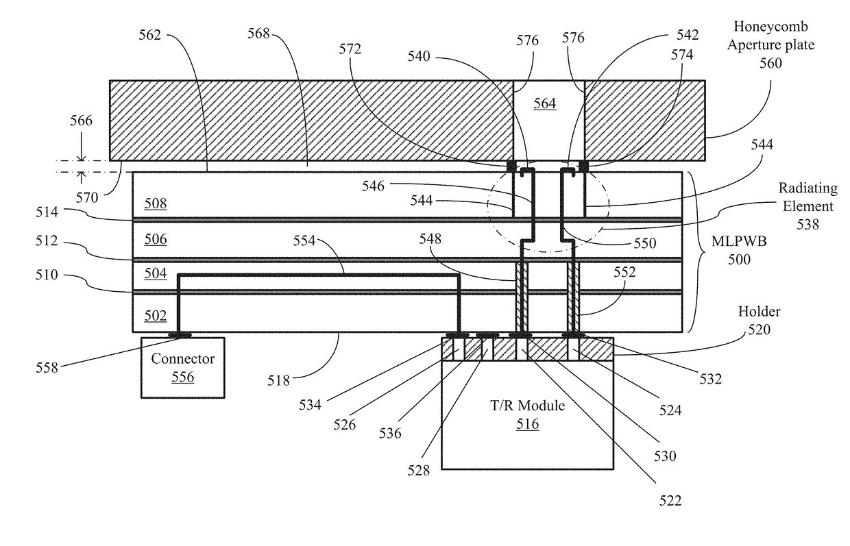
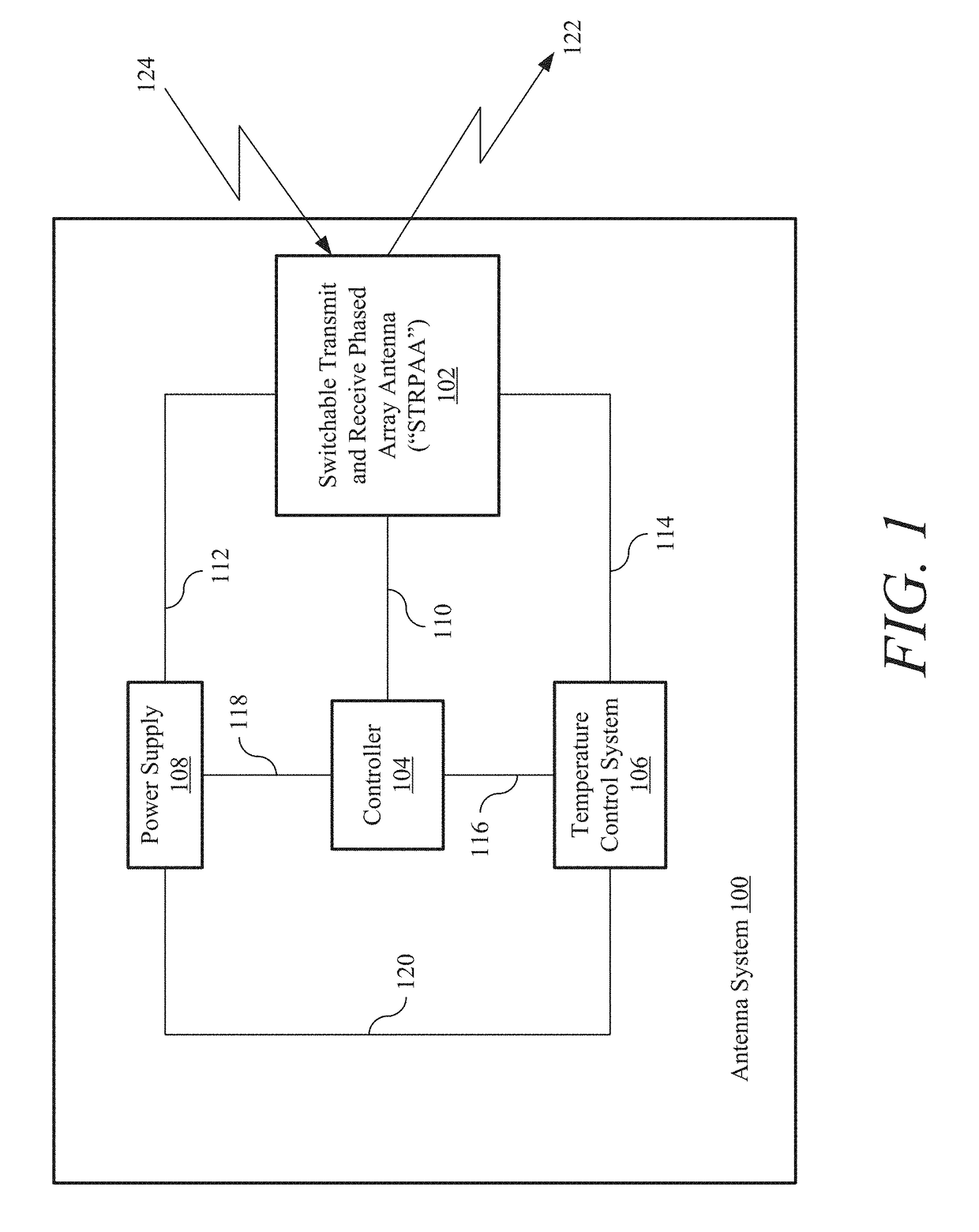
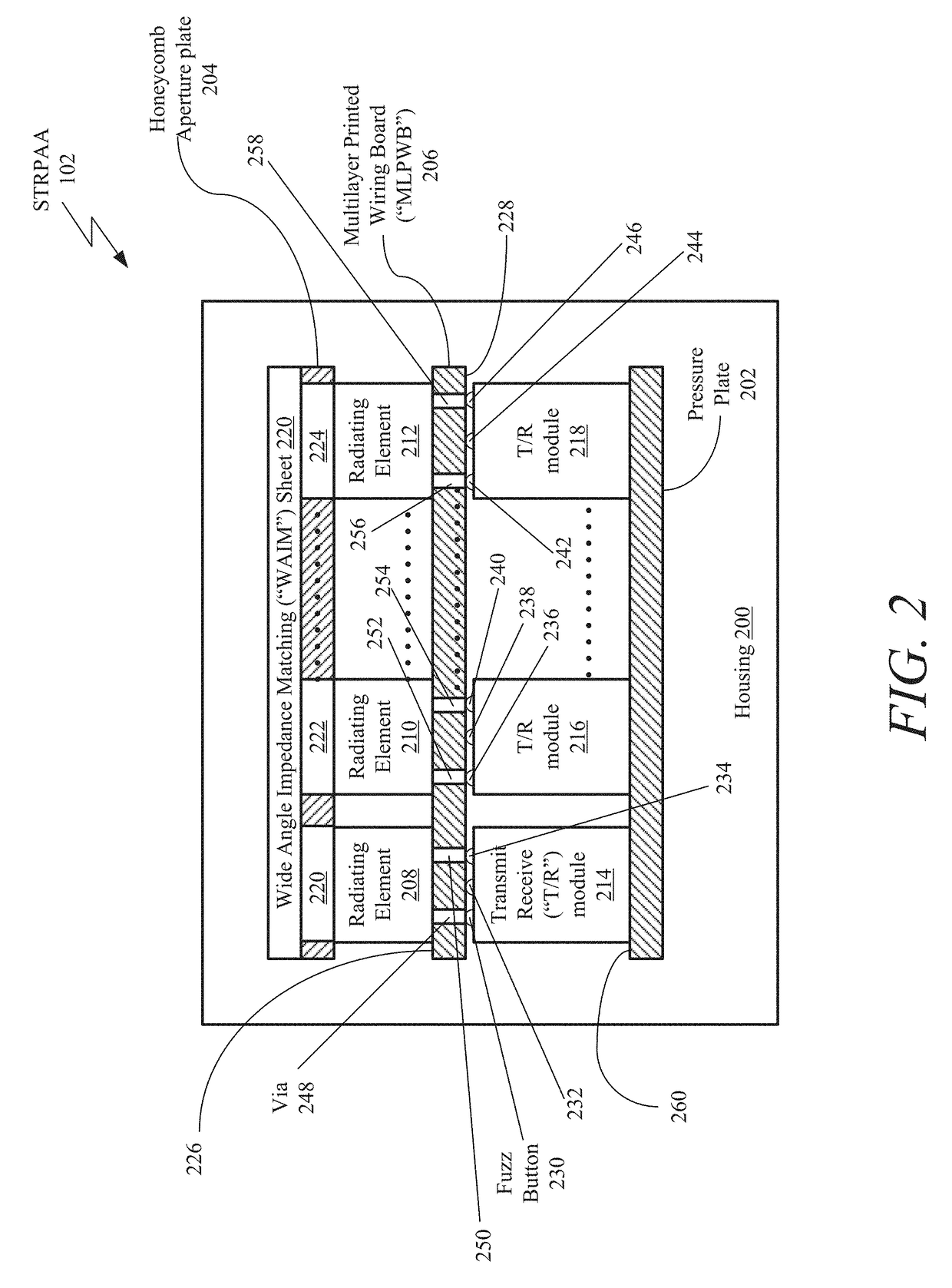
[0050]A switchable transmit and receive phased array antenna (“STRPAA”) is disclosed. The STRPAA includes a housing, a plurality of radiating elements, and a plurality of transmit and receive (“T / R”) modules. The STRPAA may also include either a first multilayer printed wiring board (“MLPWB”) configured to produce a first elliptical polarization or a second MLPWB configured to produce a second elliptical polarization within the housing.

[0051]The first MLPWB includes a first MLPWB top surface and a first MLPWB bottom surface and the second MLPWB includes a second MLPWB top surface and a second MLPWB bottom surface. The plurality of radiating elements may be attached to either the first MLPWB top surface or the second MLPWB top surface. If attached to the first MLPWB top surface, the plurality of radiating elements are attached to the first MLPWB top surface at a predetermined azimuth position while, if attached to the second MLPWB top surface, the plurality of radiating elements are ...


PUM


Abstract

A switchable transmit and receive phased array antenna (“STRPAA”) is disclosed. The STRPAA includes a housing, a plurality of radiating elements, and a plurality of transmit and receive (“T/R”) modules. The STRPAA may also include either a first multilayer printed wiring board (“MLPWB”) configured to produce a first elliptical polarization or a second MLPWB configured to produce a second elliptical polarization within the housing.

Description

CROSS-REFERENCE TO RELATED APPLICATION AND CLAIM OF PRIORITY[0001]The present patent application is a continuation-in-part (“CIP”) application, claiming priority under 35 U.S.C. §119(a) and 35 U.S.C. §120, to both U.S. patent application Ser. No. 14 / 568,660, filed on Dec. 12, 2014, titled “Switchable Transmit and Receive Phased Array Antenna,” and U.S. patent application Ser. No. 15 / 161,110, filed on May 20, 2016, titled “Switchable Transmit and Receive Phase Array Antenna,” which are hereby incorporated by reference in its entirety.BACKGROUND[0002]1. Field[0003]The present invention is related to phased-array antennas and, more particularly, to low-cost active-array antennas for use with high-frequency communication systems.[0004]2. Related Art[0005]Phased array antennas (“PAA”) are installed on various mobile platforms (such as, for example, aircraft and land and sea vehicles) and provide these platforms with the ability to transmit and receive information via line-of-sight or bey...

Claims


Application Information

Patent Timeline
Patent Type & Authority Applications(United States)
IPC IPC(8): H01Q21/22H01Q1/32H01Q9/04H01Q1/24H01Q1/38
CPCH01Q21/22H01Q1/24H01Q1/3233H01Q9/0428H01Q1/38H01P5/12H01Q1/523H01Q3/28H01Q3/36H01Q9/0435H01Q19/062H01Q21/0025H01Q21/0087H01Q21/064H01Q21/065H01Q21/245H01Q25/001
Inventor CHEN, MINGTAKEUCHI, JIMMY S.CAMERON, RODNEY D.FOSTER, MICHAEL S.DAVIS, MARK R.
Owner THE BOEING CO
Why Eureka
Try Eureka