
Slim line while in use cover and methods for making and using the same

a technology of cover and slit, applied in the direction of coupling base/case, coupling device connection, coupling device engagement/disengagement, etc., can solve the problems of cover not meeting the overall dimensions of the cover when in use, easy to be exposed to water and other contaminants, and visually disorienting

Active Publication Date: 2017-08-17
SIGMA ELECTRIC MFG
View PDF2 Cites 28 Cited by
  • Summary
  • Abstract
  • Description
  • Claims
  • Application Information

AI Technical Summary

Benefits of technology

The patent describes a while in use cover assembly for a power cord that can be easily attached to an outlet. The cover assembly includes a hinged lid, a current member, and an orientable adaptor that allows the current member to have a constant orientation within the base. The cover assembly can be attached to a socket or a junction box. The technical effect of this invention is to provide a convenient and safe way to handle power cords while in use, preventing injury and ensuring proper grounding.

Problems solved by technology

Electrical boxes are prone to exposure to water and other contaminants from the outside when mounted on exterior walls of various structures.
Such a design, however, poses aesthetic problems in that the covers protrude three or more inches from the exterior of a structure, which can be visually displeasing.
However, such covers fail to address the overall dimensions of the cover when in use, such that the cover and outlet expand to 3 inches to 3.5 inches when in use.
However, the lid can be difficult to open and the lid expands to at least 2.5 inches when in use, and thus, also fails to address the overall dimensions of the lid when in use.
There remains an unfulfilled need to provide a while in use cover that addresses the problem of bulky, unsightly while in use covers, while still providing protection from the elements.

Method used


Image

  • Slim line while in use cover and methods for making and using the same
  • Slim line while in use cover and methods for making and using the same
  • Slim line while in use cover and methods for making and using the same

Examples


embodiment 1

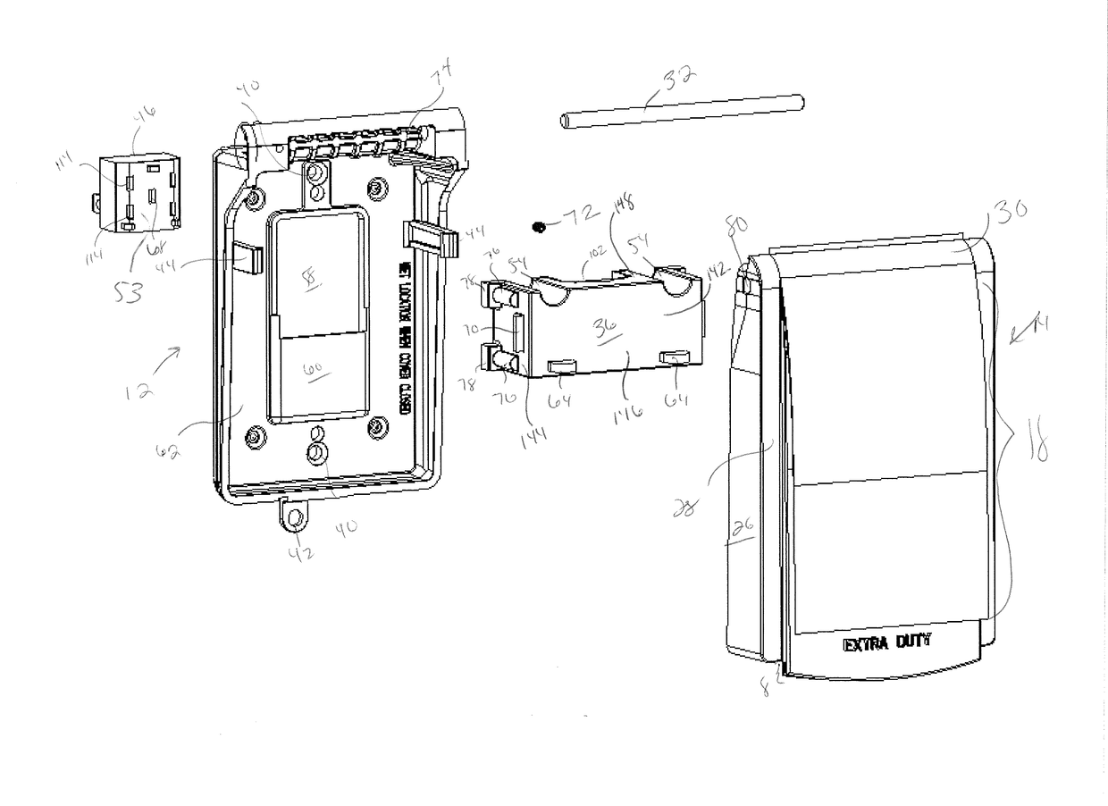
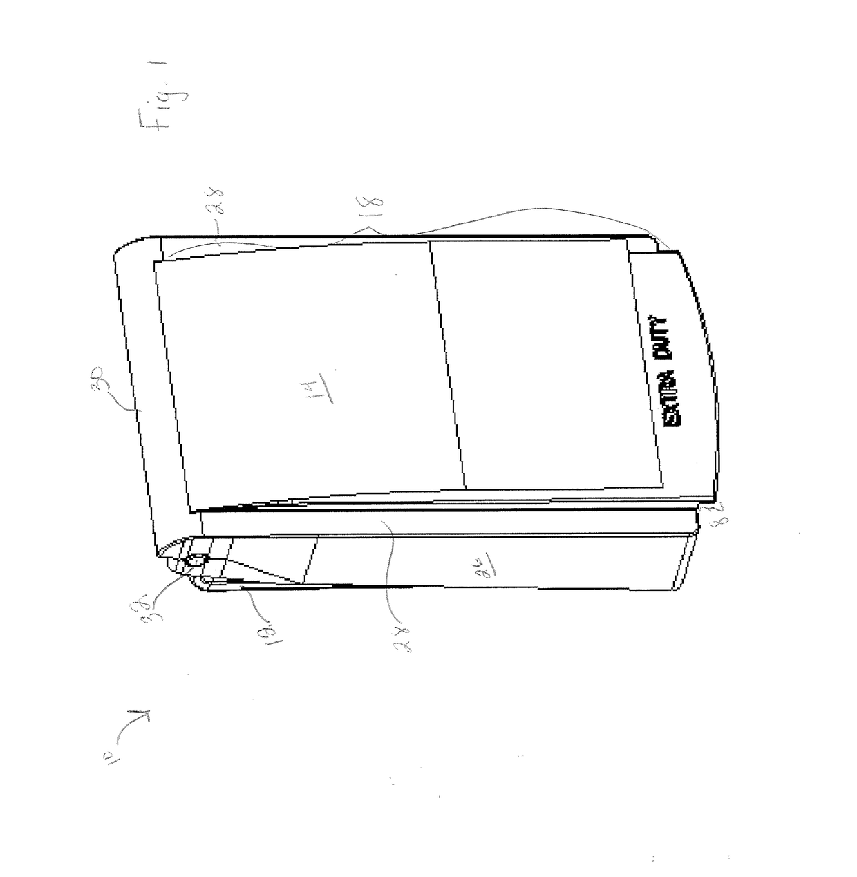
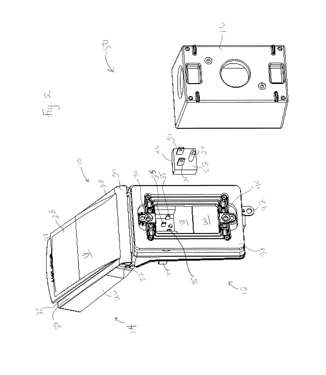
[0079] A while in use cover assembly, comprising: a lid hingedly attached to a base having a back wall; a current member attached to the base, wherein the current member comprises a face with blade apertures configured to receive a power cord plug; and an orientable adaptor attached to the current member, wherein the orientable adaptor is symmetrical about a center line and wherein the orientable adaptor allows the current member to have a constant orientation within the base; and wherein the while in use cover assembly is configured to be attached to an outlet socket.

embodiment 2

[0080] A while in use cover assembly, comprising: a lid hingedly attached to a base having a back wall; a current member attached to the base, wherein the current member comprises a plug receiving portion and an orientable adaptor receiving portion, wherein the orientable adaptor receiving portion is disposed perpendicularly to the plug receiving portion; and an orientable adaptor attached to the orientable adaptor receiving portion of the current member, wherein the orientable adaptor is symmetrical about a center line and wherein the orientable adaptor allows the current member to have a constant orientation within the base; wherein the while in use cover assembly has a constant depth, when the lid is closed, when in use and when not in use; and wherein, when the while in use cover assembly is in use, a power cord plug is attached to the current member, and a power cord extending from the power cord plug extends through a power cord exit while bending toward the back wall or towar...

embodiment 3

[0081] The while in use cover assembly of Claim 1 or Claim 2, wherein the orientable adaptor is configured to electrically connect to the outlet socket.


PUM


Abstract

A while in use cover assembly includes a lid hingedly attached to a base having a back wall; a current member attached to the base, wherein the current member comprises a face with blade apertures configured to receive a power cord plug; and a orientable adaptor attached to the current member, wherein the orientable adaptor is symmetrical about a center line and wherein the orientable adaptor allows the current member to have a constant orientation within the base; and wherein the while in use cover assembly is configured to be attached to an outlet socket.

Description

CROSS REFERENCE TO RELATED APPLICATIONS[0001]This application is a non-provisional of and claims priority to U.S. Application Ser. No. 62 / 295,840, filed Feb. 16, 2016, which is incorporated herein by reference in its entirety.TECHNICAL FIELD[0002]The instant application relates to while in use covers for protecting electrical outlets and plugs attached thereto from elements, such as water (e.g., rain, snow), dust, and / or other debris.BACKGROUND[0003]Electrical boxes are prone to exposure to water and other contaminants from the outside when mounted on exterior walls of various structures. While in use cover generally refers to a cover allowing an electrical plug to be plugged into an outlet while the cover is closed to protect the outlet and plug from the elements including weather (e.g., rain, snow), dust, and / or other debris. Typically, to allow a cover to close while the outlet is in use, the base and / or lid need to be deep enough to allow the cover to close without interfering w...

Claims


Application Information

Patent Timeline
Patent Type & Authority Applications(United States)
IPC IPC(8): H01R13/52H02G3/18H01R43/26H02G3/10H01R25/00H01R31/06
CPCH01R13/5213H01R25/006H01R31/06H02G3/18H01R43/26H02G3/10H01R13/5202H01R24/68H02G3/14
Inventor SATHYANARAYANA, ASHOK ALILUGHATTACHAVAN, VINAYAK MANOHARKHODAPE, YUVRAJ TOTARAMDIVEKAR, SHRIRAM RAMESH
Owner SIGMA ELECTRIC MFG
Learn More