Submerged pump capable of achieving automatic adjusting according to water level
An automatic adjustment and submersible pump technology, applied in the direction of liquid fuel engines, pumps, pump control, etc., can solve the problems of submersible pumps that cannot adjust the position, reduce the service life of submersible pumps, and waste manpower
- Summary
- Abstract
- Description
- Claims
- Application Information
AI Technical Summary
Problems solved by technology
Method used
Image
Examples
Embodiment 1
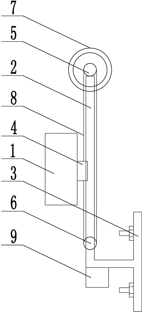
[0018] Embodiment 1: as figure 1 As shown, the liquid level automatic adjustment submersible pump of the present invention includes a submersible pump 1, which is provided with a track 2, and the track 2 is fixed on the side wall of the pool through a bracket 3, and the submersible pump 1 is installed on the track 2 through a slider 4, The top and the lower end of the track 2 are respectively provided with a driving gear 5 and a driven gear 6, the rotating shaft of the driving gear 5 is connected to the rotor of the reduction motor 7 through a shaft coupling, and the chain 8 is fixed on the slide by bypassing the driving gear 5 and the driven gear 6. At both ends of the block 4, the geared motor 7 is connected to the power supply through the control device 9.
Embodiment 2
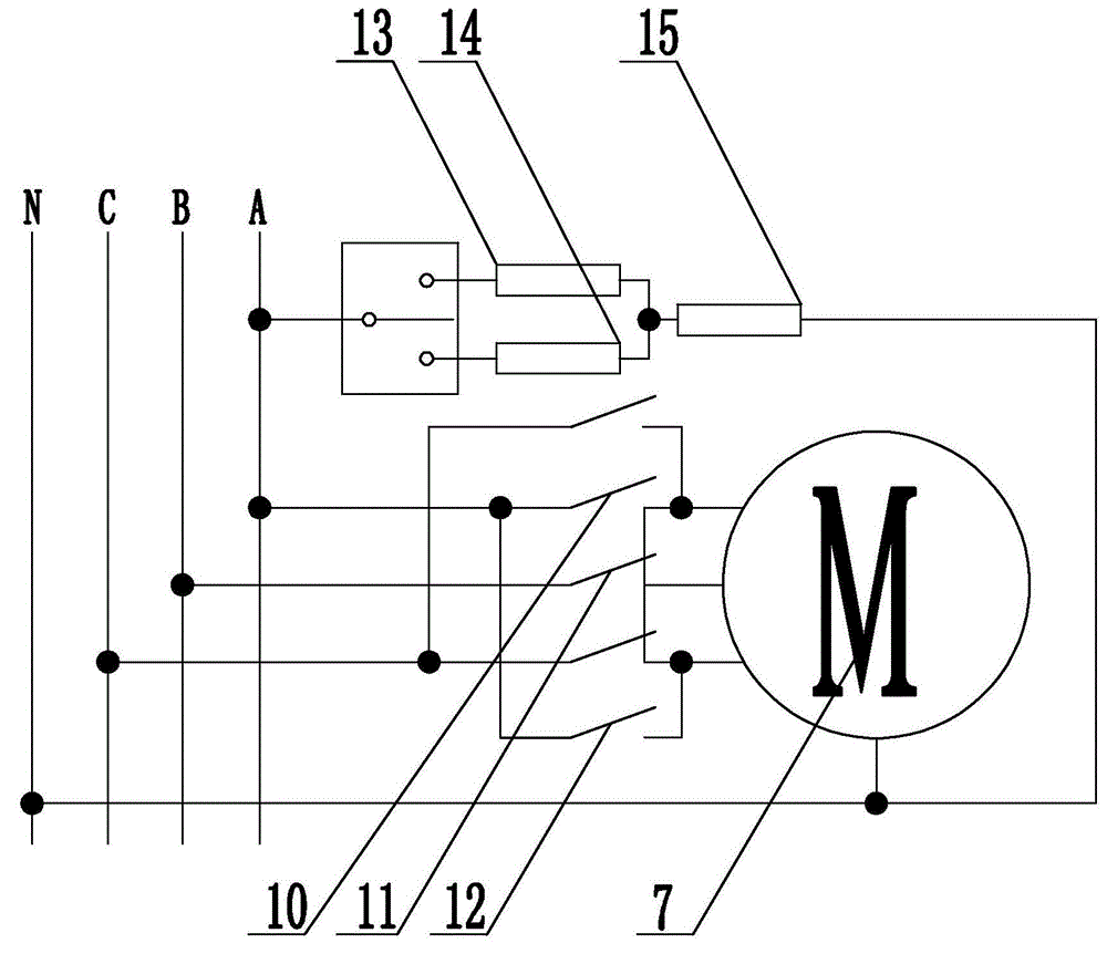
[0019] Embodiment 2: on the basis of the structure described in embodiment 1, as figure 2 As shown, the control device 9 includes a relay A, a relay B, a relay C and a trigger. The two items of the three-phase power supply are connected to the corresponding power supply terminals of the geared motor 7 through the two normally open contacts 10 of the relay A, and the other two items of the three-phase power supply One phase is connected to the corresponding power supply terminal of the deceleration motor 7 through the normally open contact 11 of the relay C, and the two phases of the three-phase power supply are connected to the opposite power supply terminal of the deceleration motor 7 through the two normally open contacts 12 of the relay B, and the relay A One end of the coil 13 of the relay B and the coil 14 of the relay B are connected to one phase of the three-phase power supply through the trigger, and the other end of the coil 13 of the relay A and the coil 14 of the re...
Embodiment 3
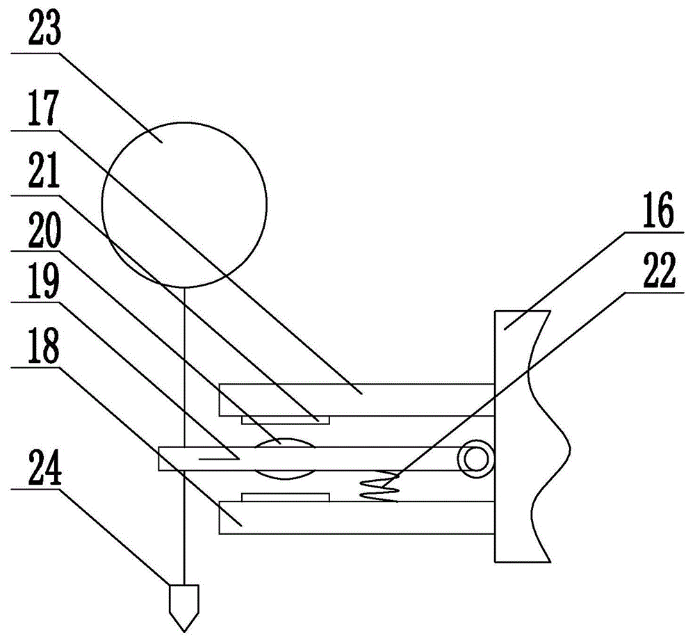
[0020] Embodiment 3: on the basis of the structure described in embodiment 2, as image 3 As shown, the trigger includes a base 16, and the base 16 is provided with an upper stopper 17 and a lower stopper 18, and a rotating shaft 19 is hinged between the upper stopper 17 and the lower stopper 18 of the base 16, and the rotating shaft 19 is provided with The moving contact 20, the upper plate 17 and the lower plate 18 are provided with a static contact 21 at a position suitable for the moving contact 20, the moving contact 20 is connected to the power supply, and the static contact of the upper plate 17 and the lower plate 18 Point 21 is respectively connected to the coil 13 of relay A and the coil 14 of relay B. A spring 22 is provided between the rotating shaft 19 and the lower stopper 18. The ends of the rotating shaft 19 exposed on the upper stopper 17 and the lower stopper 18 are respectively connected to the floating ball by wires. 23 and weight 24.
[0021] Operation st...
PUM
 Abstract
Description
Claims
Application Information
 - R&D
- Intellectual Property
- Life Sciences
- Materials
- Tech Scout
- Unparalleled Data Quality
- Higher Quality Content
- 60% Fewer Hallucinations
Browse by: Latest US Patents, China's latest patents, Technical Efficacy Thesaurus, Application Domain, Technology Topic, Popular Technical Reports.
© 2025 PatSnap. All rights reserved.Legal|Privacy policy|Modern Slavery Act Transparency Statement|Sitemap|About US| Contact US: help@patsnap.com


