
Dimple Processing Method

a processing method and compound technology, applied in the field of compound processing methods, can solve the problems of reducing the frictional resistance between the counter material and the counter material, and achieve the effects of reducing the angle of the approach, avoiding concentrating the cutting force, and beneficially prolonging the life of the cutting edg

Pending Publication Date: 2022-10-13
KANEFUSA HAMONO KOUGIYOU KK
View PDF0 Cites 0 Cited by
  • Summary
  • Abstract
  • Description
  • Claims
  • Application Information

AI Technical Summary

Benefits of technology

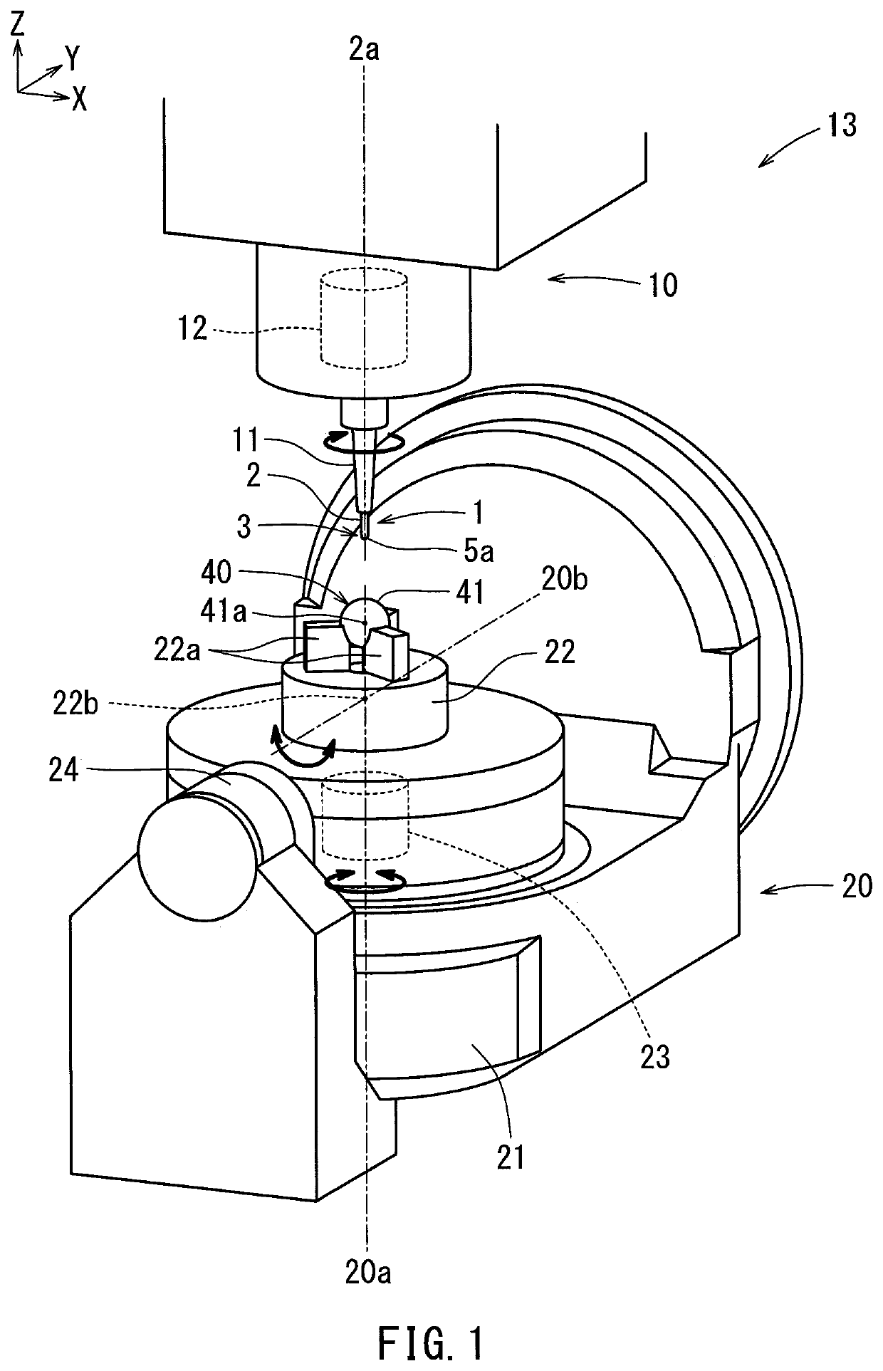
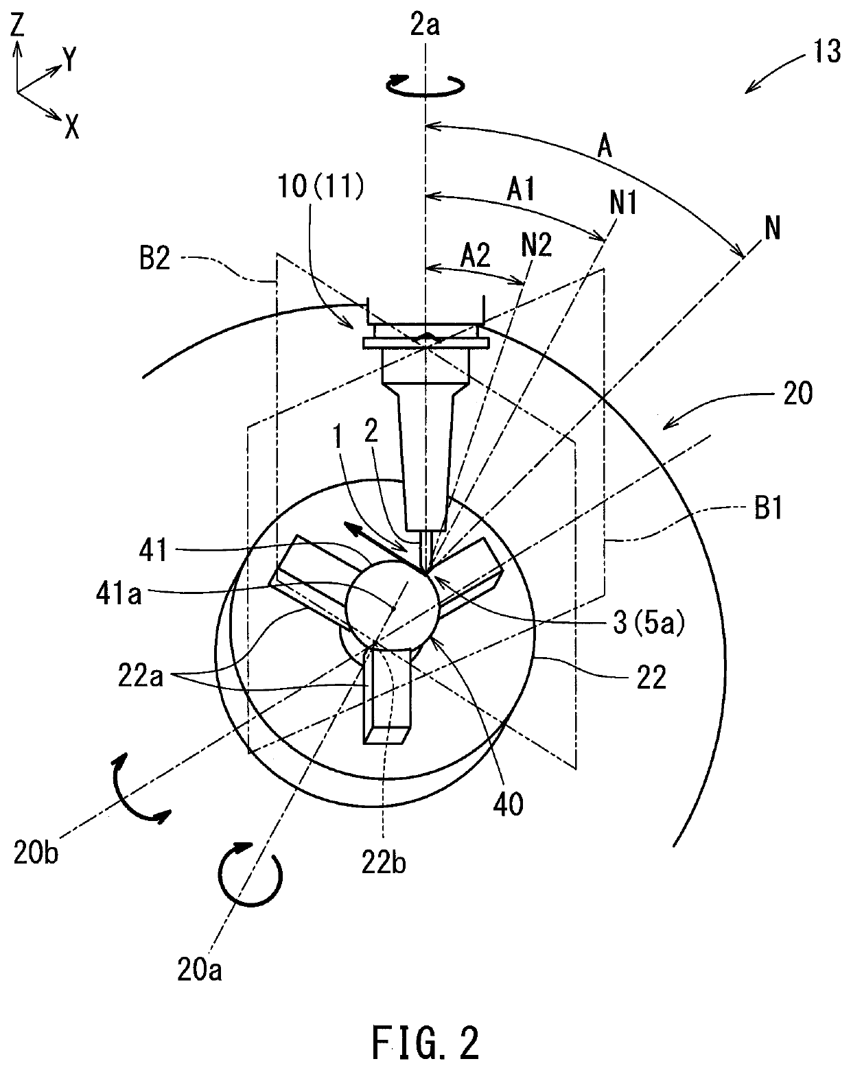
This patent describes a cutting tool or workpiece that can move in two dimensions on a flat surface. By rotating both the cutting tool and the workpiece, multiple dimples can be formed on a curved surface quickly. These dimples have a constant depth and approach angle, which reduces burrs and heat while improving reproducibility. The cutting tool has a continuous cutting edge that changes contact points with the curved surface, which benefits its longevity. The workpiece and cutting tool are rotated about three axes, which allows for the formation of dimples on the spherical portion of the curved surface and reduces approach angle. Overall, this invention improves the efficiency and quality of dimpling processes.

Problems solved by technology

This pressure may hinder the counter material from coming into contact with the workpiece, thereby reducing the frictional resistance between the counter material and the workpiece.

Method used


Image

  • Dimple Processing Method
  • Dimple Processing Method
  • Dimple Processing Method

Examples


Embodiment Construction

[0036]As previously described, dimples may be provided on the surface of a workpiece to reduce the frictional resistance generated during relative movement between the surface of the workpiece and a counter material in contact with the surface of the workpiece.

[0037]Dimples may be formed on inner walls of tubular members, such as engine cylinders and turbochargers, and joint surfaces of artificial joints to reduce frictional resistance. U.S. Pat. No. 9,872,772 discloses an artificial joint in which dimples are formed on a spherical surface of the joint. Conventional dimples are formed by, for example, laser machining, shot blasting, etching, press molding, or the like. In such processing methods, it can be difficult to reduce an approach angle 0 of the dimples 82 formed on the surface 81, as shown in FIG. 20. It should be appreciated that FIG. 20 schematically illustrates one of the present embodiments, instead of a conventional structure, but nonetheless indicates the approach angl...


PUM

PropertyMeasurementUnit
rake angleaaaaaaaaaa
inclination angleaaaaaaaaaa

Abstract

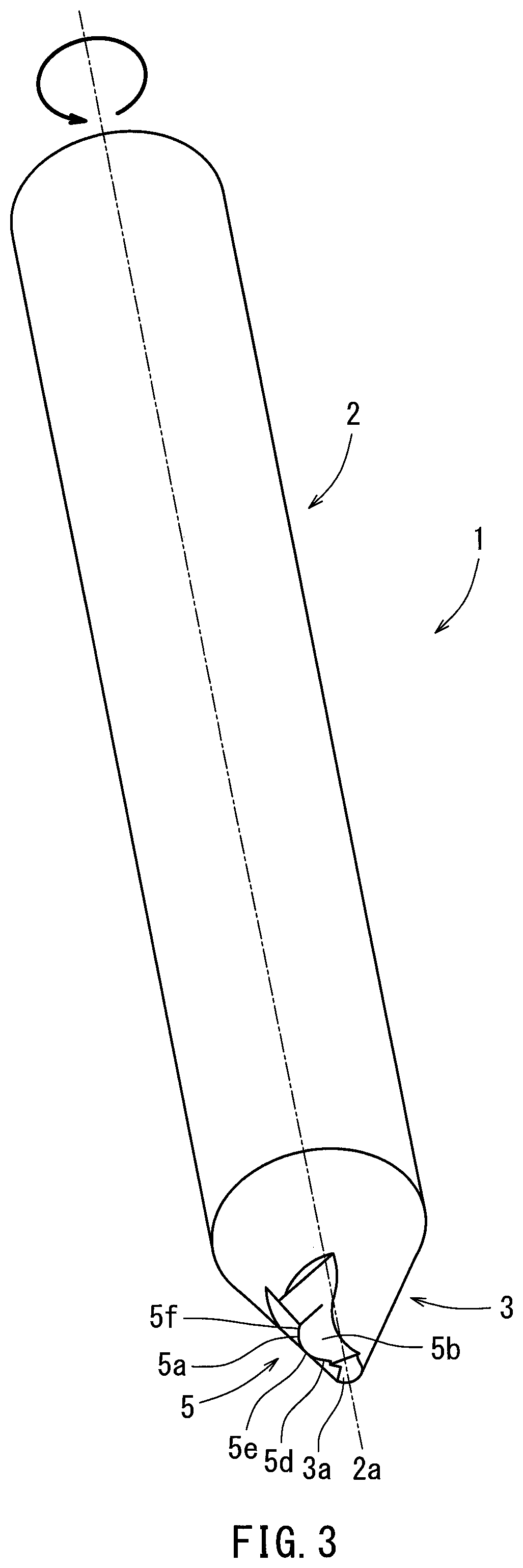
In a dimple processing method for forming dimples on a curved surface of a workpiece, a cutting tool having a cutting edge on a rod-shaped body is rotated about a central axis of the cutting tool. The workpiece is rotated about a first axis. The cutting tool or the workpiece moves on a virtual plane through which the first axis passes or on a plane parallel to the virtual plane. The cutting tool or the workpiece moves such that the tip end of the cutting tool follows the curved surface of the workpiece. The cutting edge forms one or more dimple on the curved surface each time the cutting tool rotates.

Description

CROSS-REFERENCE TO RELATED APPLICATIONS[0001]The present application is a 35 U.S.C. § 371 U.S. National Phase entry of, and claims priority to, PCT Application PCT / JP2020 / 031089 filed Aug. 18, 2020, which claims priority to Japanese Patent Application No. 2019-167563 filed Sep. 13, 2019, both of which are hereby incorporated herein by reference in their entireties for all purposes.STATEMENT REGARDING FEDERALLY SPONSORED RESEARCH OR DEVELOPMENT[0002]Not applicable.BACKGROUND[0003]The present disclosure relates generally to dimple processing methods for forming dimples on curved surfaces of workpieces.[0004]Dimples defined by a plurality of fine recesses may be formed on a surface of workpieces made of, for example, aluminum, copper alloys, castings thereof, steel materials, or resins. For example, dimples may be formed on a metal workpiece by scraping. A satin pattern may be formed on a surface of a workpiece using a plurality of dimples. Dimples may be provided on the surface of a w...

Claims


Application Information

Patent Timeline
Patent Type & Authority Applications(United States)
IPC IPC(8): B23C3/16B23P15/00B23C3/04
CPCB23C3/16B23P15/00B23C3/04B23C2265/36B23C2210/084B23C2210/201B23C2210/242B23C2220/04B23C5/14B23C3/026A61F2/30G05B19/182
Inventor SATO, TOSHIKIKANDA, YASUYUKINIIMI, TATSUYA
Owner KANEFUSA HAMONO KOUGIYOU KK
Learn More