
Downhill Wire Bonding for QFN L - Lead

Inactive Publication Date: 2008-11-20
TEXAS INSTR INC
View PDF6 Cites 12 Cited by
  • Summary
  • Abstract
  • Description
  • Claims
  • Application Information

AI Technical Summary

Benefits of technology

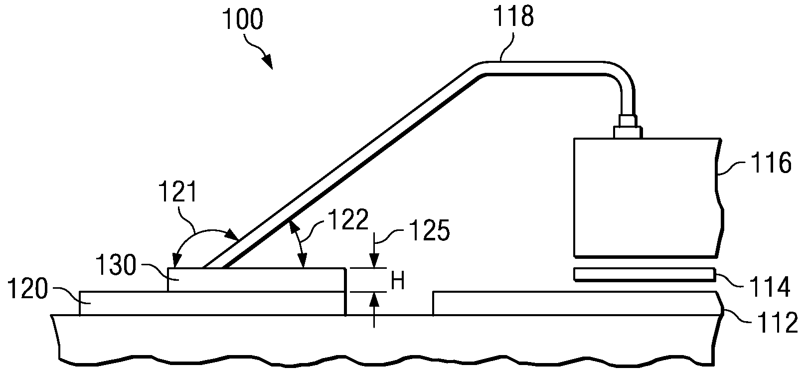
[0009]In accordance with the present invention, the above noted problem which is inherent to downhill wire bonding of the lead frames is advantageously addressed by reducing the angle of approach of the capillary during the downhill wire bonding process between various components of the semiconductor. The stitch platform is welded with a gold wire that loops from the semiconductor die to the lead finger or stitch platform. It is done using the thermosonic process meaning a welding process at high temperature with ultrasound.
[0011]There are two factors that enable to reduce the angle of approach of the capillary: increase the thickness of the lead finger or the stitch platform and / or reduce the height by which the capillary is lifted vertically from the semiconductor die before it loops over to the lead finger or the stitch platform.
[0020](a) etching each said plurality of lead fingers to increase lead finger thickness;
[0025]The embodiments advantageously provide an improved QFN (L-lead semiconductor package which comprises an integrated circuit bonded to a lead frame die with an adhesive, said integrated circuit having a plurality of die pads; and a plurality of lead fingers electrically wire bonded with said plurality of die pads of said integrated circuit; wherein each said plurality of lead fingers presents an increased stitch platform thickness.

Problems solved by technology

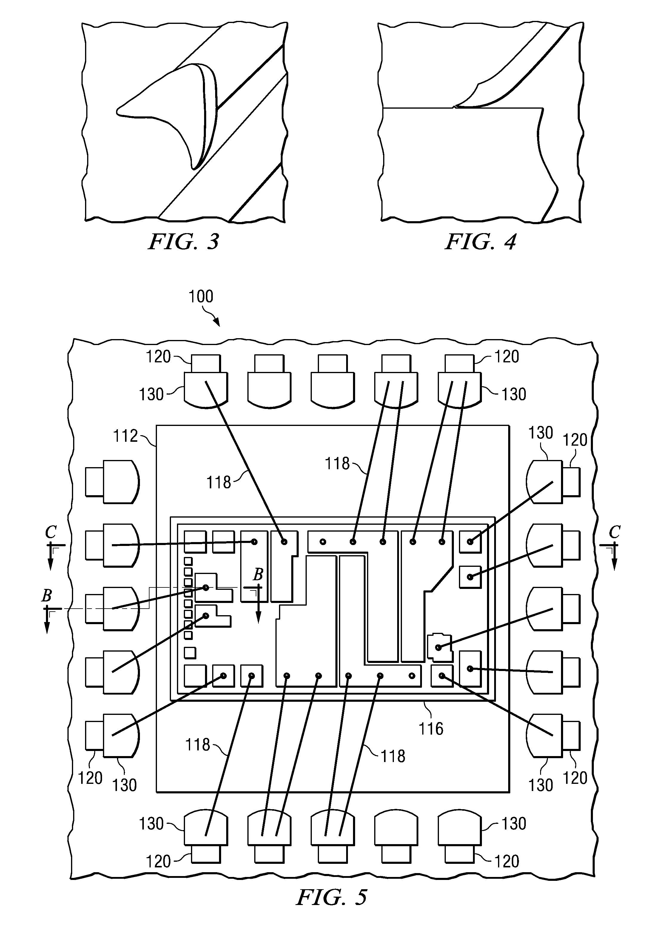
This causes the heel of the stitch bond to crack or to break away from the surface of contact and therefore to be unreliable, which leads to diminished yield due to faulty bonding.
As for traditional packaging, broken heel stitch is a serious reliability issue which cannot always be detected by test.

Method used


Image

  • Downhill Wire Bonding for QFN L - Lead
  • Downhill Wire Bonding for QFN L - Lead
  • Downhill Wire Bonding for QFN L - Lead

Examples


Embodiment Construction

[0036]The preferred embodiment of the present invention and its advantages are best understood by referring to the drawings, like numerals being used for like and corresponding parts of the various drawings.

[0037]The present invention is directed towards a device and process for reducing the mechanical and thermal stress of stitch bonding by reducing the angle of approach of the downhill wire bonding.

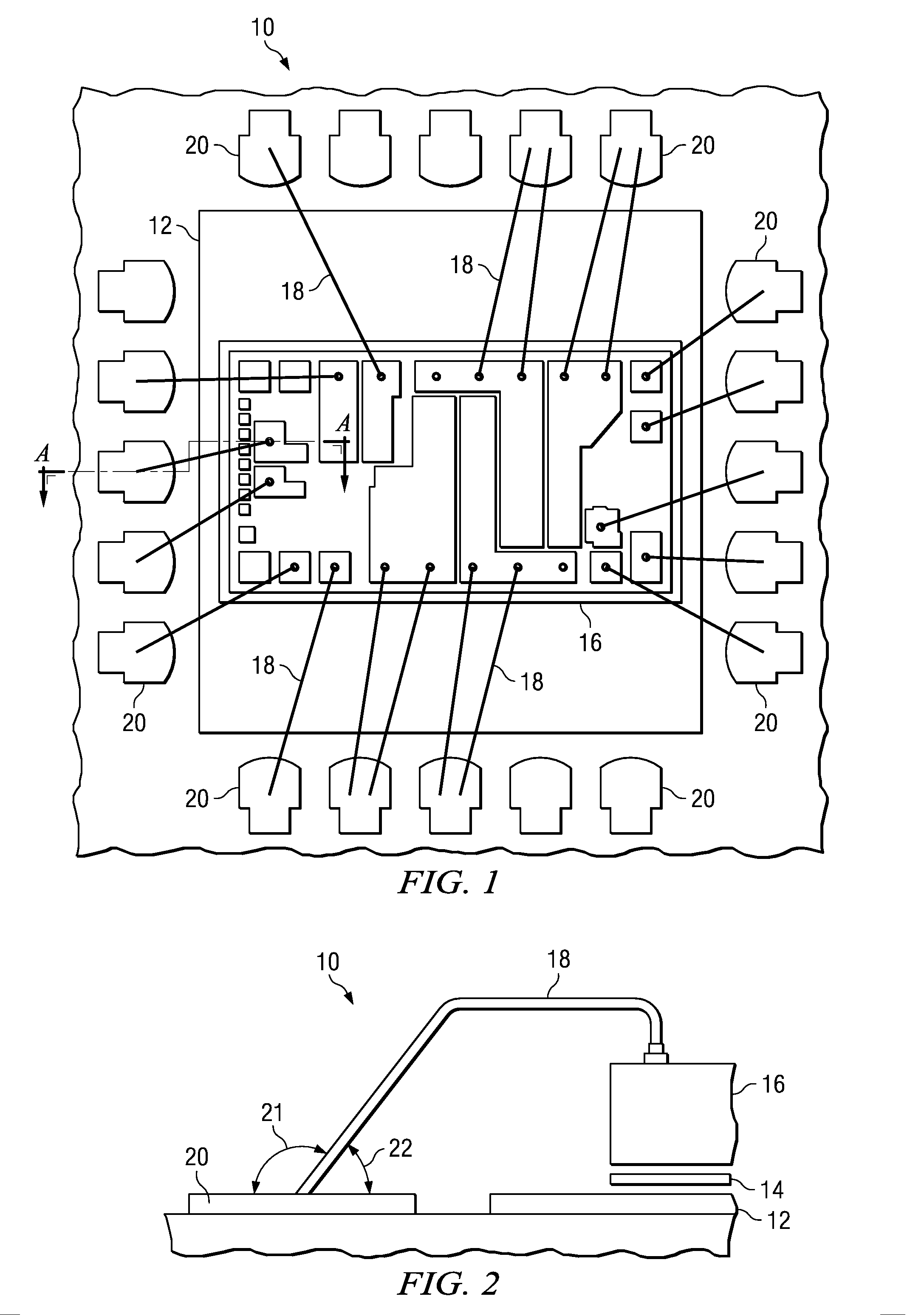
[0038]in FIG. 1, a standard semiconductor 10 is shown wherein a die 16 is coupled to a lead frame die 12. Die 16 and lead frame die 12 are bonded to one another, and may be electrically connected to one another. In the example shown in FIG. 1, die 16 comprises an integrated circuit wherein a plurality of conductive leads 18 are operable to connect die 16 to a plurality of lead fingers 20.

[0039]FIG. 2 shows a partial cross-sectional view A-A of the standard semiconductor 10 of FIG. 1. And more particularly, FIG. 2 shows how conductive leads 18 couple die 16 to the plurality of lead finge...


PUM


Abstract

Downhill wire bonding process for QFN is performed with a capillary using goldwire that connects die (the Integrated Circuit or the substrate) and the stitch platform also called lead fingers. The goldwire is molten into a ball by applying high current. The molten ball is compressed against the bond pads of the integrated circuit using high temperature and ultrasonic energy. To complete the connection, the capillary is lifted vertically from the bond pads of the die or integrated circuit to loop over to the lead finger so that the goldwire is compressed against the lead finger with a reduced angle of approach of the capillary. Downhill wire bonding of the lead frames is advantageously addressed by increasing the thickness of the stitch platform so as to reduce the angle of approach of the capillary during the downhill wire bonding process between various components of the semiconductor.Another way of reducing the angle of approach of the capillary is also reduce the height by which the capillary is lifted vertically from the die or integrated circuit before it loops over to the lead fingers.

Description

FIELD OF THE INVENTION [0001]The invention relates to the packaging of semiconductor devices and more particularly to a device and a method of downhill wire bonding between the bond pads of the integrated circuit and lead fingers while lessening thermal and mechanical stress of downhill wire bonding by reducing the angle of approach of the capillary in the downhill wire bonding.BACKGROUND OF THE INVENTION [0002]Various techniques are used for packaging integrated circuits and for wire bonding between different locations of a semiconductor die, as well as between the semiconductor die and an external location such as a lead finger on a lead frame. The lead fingers are generally formed of copper or a copper alloy such as A42 and the bond pads on the die are generally aluminum. Wire bonding is performed by placing a capillary over a bond pad of the semiconductor die for making a ball bond with a ball of the wire extending out of the capillary and bonding the ball to the bond pad. The c...

Claims


Application Information

Patent Timeline
IPC IPC(8): H01L21/44
CPCH01L23/4952H01L23/49541H01L23/49582H01L24/05H01L24/06H01L24/32H01L24/45H01L24/48H01L24/49H01L24/83H01L24/85H01L2224/04042H01L2224/05552H01L2224/05553H01L2224/05556H01L2224/05624H01L2224/0603H01L2224/45124H01L2224/45139H01L2224/45144H01L2224/45155H01L2224/45164H01L2224/45166H01L2224/4809H01L2224/48095H01L2224/48247H01L2224/48455H01L2224/48465H01L2224/49111H01L2224/49113H01L2224/49171H01L2224/73265H01L2224/78301H01L2224/83101H01L2224/8385H01L2224/85205H01L2224/92247H01L2924/01005H01L2924/01013H01L2924/01022H01L2924/01028H01L2924/01029H01L2924/01046H01L2924/01047H01L2924/01079H01L2924/01082H01L2924/07802H01L2924/14H01L2924/15153H01L2924/1517H01L2924/00014H01L2224/2919H01L2924/01006H01L2924/01033H01L2924/0665H01L2224/78H01L2924/00H01L2224/32245H01L2224/48724H01L2224/48624H01L2924/00012H01L2924/3512H01L2924/351H01L2224/45147H01L2224/48824H01L24/73H01L2224/45015H01L2924/207
Inventor CHIA, MENG THEE
Owner TEXAS INSTR INC
Learn More