
Inkjet printing apparatus

a printing apparatus and inkjet technology, applied in printing, other printing apparatus, etc., can solve the problems of increasing reducing the amount of paper flotation, and unevenness by wind, so as to improve printing accuracy and accurate control of transportation speed

Active Publication Date: 2018-01-16
DAINIPPON SCREEN MTG CO LTD
View PDF15 Cites 0 Cited by
  • Summary
  • Abstract
  • Description
  • Claims
  • Application Information

AI Technical Summary

Benefits of technology

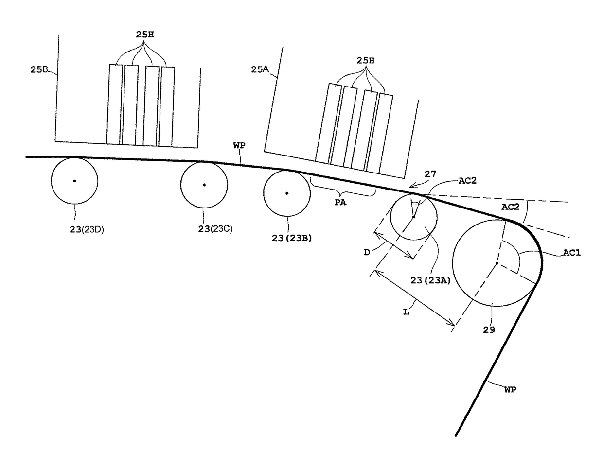
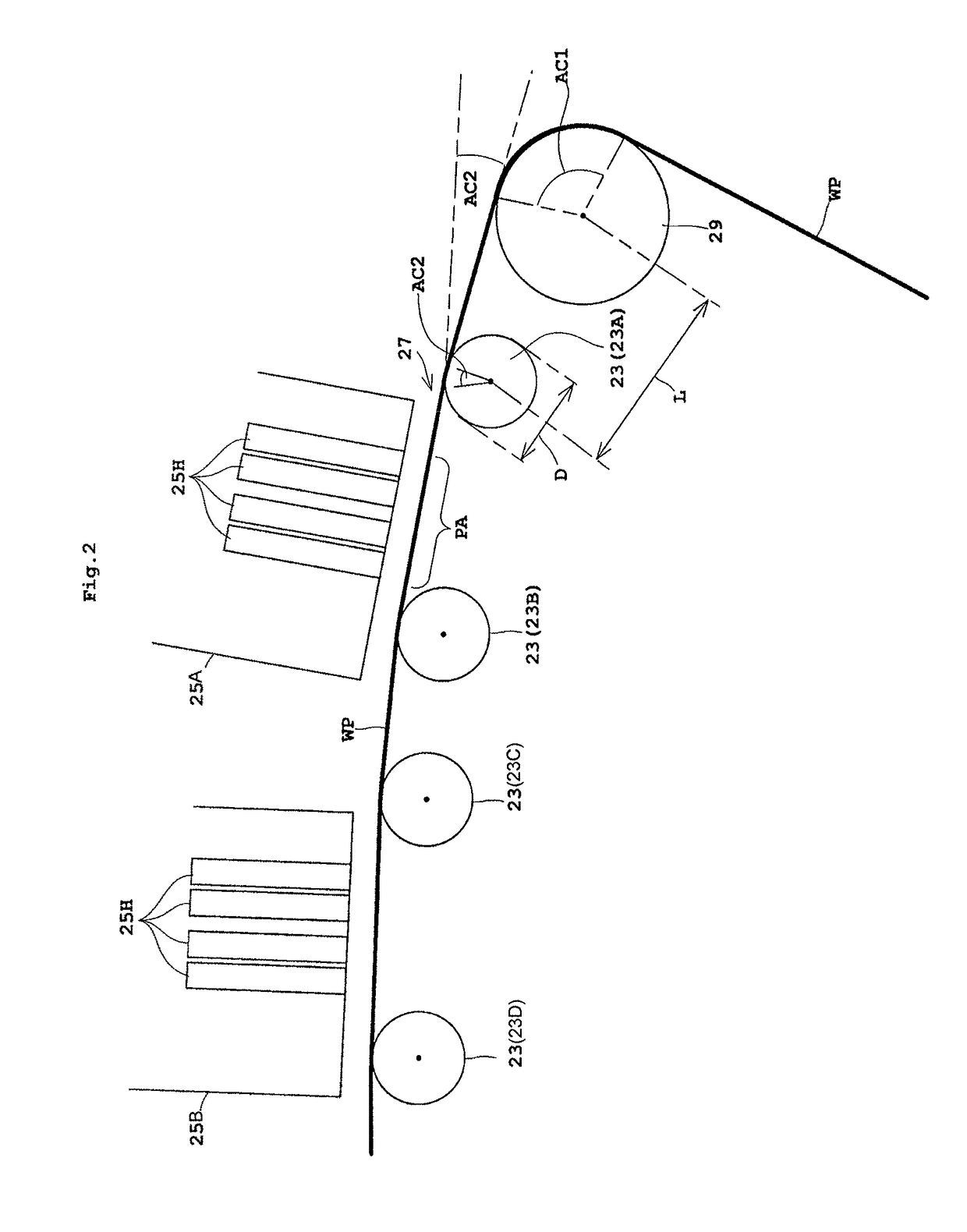
The present invention provides an inkjet printing apparatus with improved printing accuracy. The invention includes a design that reduces the approach angle of the print medium relative to the printing area and prevents roller slipping, resulting in reduced paper flotation and unevenness by wind. The first transport roller has a larger winding angle than the second transport roller, while the second transport roller has a smaller winding angle. By setting these angles within specific ranges, the invention prevents print medium slide and achieves better printing accuracy. The first transport roller can be positioned close to the printing unit, reducing air intake and further improving printing accuracy. The encoder can also be placed close to the printing unit to provide more accurate control of the transport speed, ensuring better printing accuracy.

Problems solved by technology

Specifically, a paper flotation amount decreases but unevenness by wind increases that is caused by air caught upon delivery of the printing sheet as the approach angle to the printing unit is close to 0 degree. In addition, the unevenness by wind decreases at a given approach angle to the printing unit.
On the other hand, the printing sheet delivered at the given approach angle is not controllable to cause an increased paper flotation amount.

Method used


Image

  • Inkjet printing apparatus
  • Inkjet printing apparatus
  • Inkjet printing apparatus

Examples


Embodiment Construction

[0027]The following describes in detail preferred embodiments of the present invention with reference to drawings.

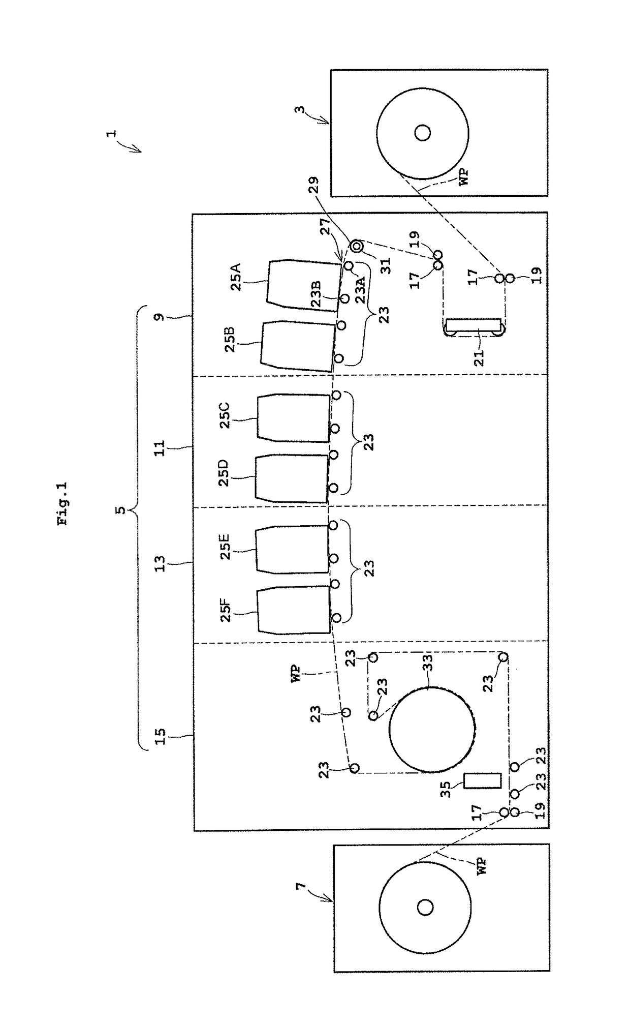
[0028]FIG. 1 is a schematic side view of an inkjet printing system according to one embodiment of the present invention.

[0029]The inkjet printing system 1 according to one embodiment of the present invention includes a paper feeder 3, an inkjet printing apparatus 5, and a take-up roller 7.

[0030]The paper feeder 3 holds long web paper WP in a roll form to be rotatable about a horizontal axis. The paper feeder 3 unwinds and feeds the web paper WP to the inkjet printing apparatus 5.

[0031]The paper feeder 3 holds the web paper WP to be rotatable about the horizontal axis. The paper feeder 3 unwinds and feeds the web paper WP to the inkjet printing apparatus 5. The inkjet printing apparatus 5 performs printing onto the web paper WP received from the paper feeder 3. The take-up roller 7 winds up the web paper WP printed by the inkjet printing apparatus 5 about the horizontal a...


PUM


Abstract

Provided is an inkjet printing apparatus including a first transport roller disposed on a transport path transporting a long print medium, a second transport roller disposed on the transport path downstream of the first transport roller, a print medium holder disposed downstream of the second transport roller, and a recording unit discharging ink droplets to a printing area of the print medium, and performing recording operation, the print medium being transported on the transport path. The first transport roller has a first winding angle upon contact to the print medium. The second transport roller has a second winding angle upon contact to the print medium. The first winding angle is larger than the second winding angle. The first winding angle is equal to or more than 75 degrees. The sum of the first and second winding angles is equal to or more than 80 degrees.

Description

TECHNICAL FIELD[0001]The present invention relates to an inkjet printing apparatus performing printing of characters or images onto a print medium by discharging ink droplets while moving the print medium and printing heads relatively.BACKGROUND ART[0002]With such an apparatus currently used, a print format has been switched from transaction printing to POD (Print on Demand) printing. The transaction printing performs typical printing onto continuous-form paper. The POD printing often performs various types of printing depending on a print medium such as exclusive paper for inkjet or coated paper. The POD printing requires printing with higher accuracy.[0003]Examples of the apparatus performing high-accurate printing include the following. For instance, a first apparatus (see, for example, Japanese Patent No. 4518584A) and a second apparatus (see, for example, Japanese Unexamined Patent Publication No. H06-70112A) have been suggested. Specifically, the first apparatus has devised ar...

Claims


Application Information

Patent Timeline
Patent Type & Authority Patents(United States)
IPC IPC(8): B41J15/04
CPCB41J15/04
Inventor YAMAMOTO, TAKAHARUYAMASHITA, SHINSUKEMORIZONO, OSAMU
Owner DAINIPPON SCREEN MTG CO LTD
Learn More