Communication device

a communication device and bus technology, applied in the field of communication devices, can solve the problems of limiting data amount and putting restrictions on the bus structure, and achieve the effect of facilitating/lightening data amount restrictions and facilitating/lightening bus structur

Active Publication Date: 2017-08-17
DENSO CORP
View PDF2 Cites 3 Cited by
  • Summary
  • Abstract
  • Description
  • Claims
  • Application Information

AI Technical Summary

Benefits of technology

[0008]According to the above, the abnormality that causes an interruption of the bus is worked around by switching the routing of the transmission information, i.e., by not using the interrupted bus for the input and output of the transmission information, which eases/lightens the data amount restriction conventionally put o

Problems solved by technology

However, the communication device in the patent document 1 is effective only when all of the ECUs are connected to two buses,

Method used


Image

  • Communication device
  • Communication device
  • Communication device

Examples


first embodiment

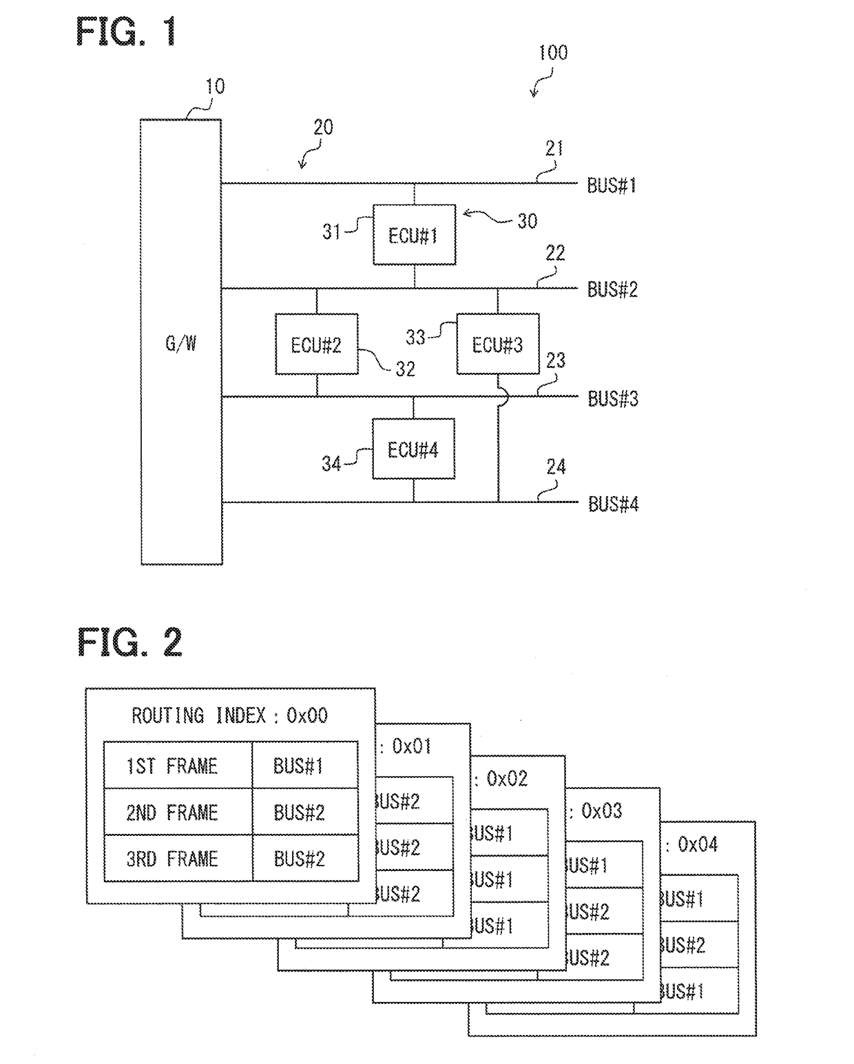
[0027]The first, with reference to FIGS. 1 and 2, the configuration of a communication device concerning the present embodiment is described.

[0028]The communication device in the present embodiment is a device including a gateway ECU that controls a “traffic” of the communication network for the data transmission performed by plural ECUS disposed in, for example, an automotive vehicle.

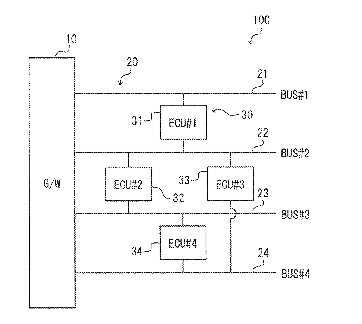
[0029]As shown in FIG. 1 a communication device 100 is provided with a gateway section 10 that is equivalent to the above-mentioned gateway ECU, two or more (i.e., plural) buses 20 connected to the gateway section 10, and two or more (i.e., plural) controllers 30 connected to the buses 20.

[0030]The gateway section 10 is a device that controls and adjusts the use of the buses 20, i.e., which one of the buses 20 the controller 30 should use for the transmission of the transmission data.

[0031]The gateway section 10 is connected to all of the buses 20 shown in FIG. 1, and is connected to all of the control...

second embodiment

[0079]In the above-described example of the first embodiment, when the first bus 21 is interrupted in addition to the third bus 23, the input to and the output from the first ECU 31 are all assigned to the second bus 22 by changing the routing index.

[0080]In such case, as shown by the lower part in FIG. 10 as well as by FIG. 12, the input of the frames to and the output of the frames from the first ECU 31 and the second ECU 32 all concentrate on the second bus 22.

[0081]Thus, a gateway section 11 in a communication device 110 of the present embodiment is provided with a load detector 40 that detects a load of the bus 20, as shown in FIG. 13. Other than having the load detector 40, the configuration of the bus 20 and the controller 30 is the same as that of the first embodiment.

[0082]The load detector 40 is connected to all of the buses 20 that are connected to the gateway section 11, and monitors a frame flow rate, or a pattern table setting condition.

[0083]The operation flow of the ...


PUM


Abstract

A communication device includes a plurality of controllers, a plurality of buses that transmit transmission information, and a gateway to which the plurality of buses are collectively connected. Each of the plurality of controllers has a pattern table that defines, for each piece of the transmission information, a transmission bus pattern, and controls the input and output of the transmission information according to the pattern table. Each of the plurality of controllers is connected to at least two buses, and outputs, to the gateway via all of the connected buses, check information for a confirmation of connections to the connected buses. The gateway determines an interrupted bus from which no check information is input, and outputs, to each of the plurality of controllers, a route switch instruction instructing use of a pattern table that does not include the interrupted bus(es).

Description

CROSS REFERENCE TO RELATED APPLICATION[0001]The present application is based on and claims the benefit of priority of Japanese Patent Application No. 2016-024242, filed on Feb. 11, 2016, the disclosure of which is incorporated herein by reference.TECHNICAL FIELD[0002]The present disclosure generally relates to a communication device that controls communication of a control device that is connected to two or more buses.BACKGROUND INFORMATION[0003]A patent document, Japanese Patent Laid-Open No. 2008-271040 (Patent document 1) listed below discloses a route switching scheme that switches one bus to the other, i.e., to an alternative, bus, when one bus has abnormality and becomes interrupted, under control of a communication device that controls communication of plural Electronic Control Units (ECU) that are respectively connected to both of two specific buses. Such a communication device enables the communication via the alternative bus by limiting a data amount of the communication v...

Claims


Application Information

Patent Timeline
IPC IPC(8): H04L12/937H04L12/803H04L12/933H04L45/28
CPCH04L49/254H04L47/125H04L49/102H04L12/40189H04L12/4625H04L12/66H04L12/46H04L12/28
Inventor KAWADA, HIROYUKI
Owner DENSO CORP
Why Eureka
Try Eureka