
Method for determining a pose of an at least semi-autonomously driving vehicle with the aid of landmarks that are specifically selected and transmitted from a back-end server

a technology of at least semi-autonomous driving and landmarks, applied in the direction of navigation instruments, instruments, image enhancement, etc., can solve the problems of putting an unnecessary strain on the capacity of an available bandwidth of the communication channel, unable to reliably model the surroundings under all lighting conditions, and no longer sufficien

Active Publication Date: 2019-04-18
ROBERT BOSCH GMBH
View PDF0 Cites 0 Cited by
  • Summary
  • Abstract
  • Description
  • Claims
  • Application Information

AI Technical Summary

Benefits of technology

The present invention provides a method for determining the pose of a semi-autonomously driving vehicle using landmarks that are sensed based on environmental influences. By selectively transmitting only the necessary data from a back-end server to the vehicle control system, the method reduces the amount of data processing required and the computing capacity needed. The use of landmarks and localization scenarios also improves the accuracy of the vehicle pose and reduces the amount of data transmitted from the back-end server. Overall, the method provides a higher quality of data and a safer driving experience for the vehicle.

Problems solved by technology

In semi-autonomously driving vehicles, in particular, in future, fully-autonomously driving vehicles, the pure GPS navigation for guiding the vehicle is no longer sufficient and new systems must be applied, which detect the immediate surroundings of the vehicle and assume the guidance of the vehicle, in particular, by recognizing landmarks.
For example, a roadway marking on a wet roadway, in particular, during darkness, may not reliably serve as a landmark, since a wet roadway, in particular, during darkness and in wet conditions may reflect, so that corresponding detectors may not be activated, however, other detectors continue to function in these weather conditions, for example, active light sources.
Signal systems, for example, are generally easily detectable regardless of the weather conditions, whereas in the case of visually operating detection systems with actual objects in the immediate surroundings of the vehicle, for example, it is not possible to reliably model corresponding surroundings under all lighting conditions.
If all landmarks from the map are communicated with the aid of the back-end server to the vehicle control system, a significant information density is then created, which puts an unnecessary strain on the capacity of an available bandwidth of the communication channel between the back-end server and the vehicle control system of the vehicle.
The computing capacity of the vehicle control system is also limited on the hardware side, so that it is desirable to reduce the amount of data transmitted by the back-end server to the vehicle control system and detector algorithms triggered as a result.
While the light conditions are comparable during rush-hour traffic in the morning, the dense traffic nevertheless results in a very high masking rate.
Hence, the traffic signs at this time of day are not detectable or only unreliably detectable and are therefore not transmitted to the vehicle.
Because of the less advantageous detector algorithms for the street lights, however, the traffic signs are again transmitted as the density of the traffic decreases.

Method used


Image

  • Method for determining a pose of an at least semi-autonomously driving vehicle with the aid of landmarks that are specifically selected and transmitted from a back-end server

Examples


Embodiment Construction

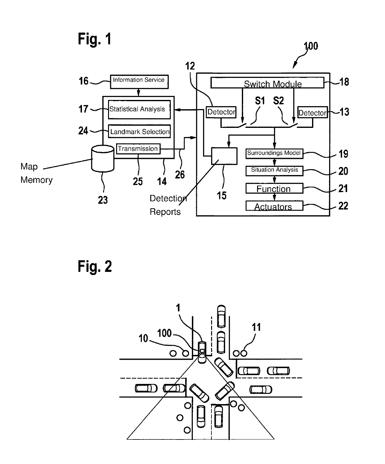
[0027]FIG. 1 shows a vehicle control system 100, including a detailed depiction of individual components. Also depicted is a back-end server 14 for receiving detection reports 15 from vehicle control system 100 and for communicating landmark data to vehicle control system 100 with the aid of a communication channel.

[0028]Vehicle control system 100 includes multiple detectors 12 and 13, merely two detectors 12, 13 being shown by way of example. With a module 18, it is possible to switch on, switch off or switch over detectors 12, 13 with the aid of switches S1 or S2, regardless of which type of landmarks 10 or 11 is to be recognized.

[0029]If either detector 12 or detector 13 or both detectors 12 and 13 is or are activated, a surroundings model 19 may be ascertained so that following a situation analysis 20, a function 21 may finally be provided, with which an action for guiding vehicle 1 is output using a system of actuators 22.

[0030]Also schematically shown, in addition to vehicle c...


PUM


Abstract

A method for determining a pose of an at least semi-autonomously driving vehicle with the aid of landmarks, the vehicle including detectors, with which the landmarks are detected, and a back-end server being provided, with which the landmark data of the landmarks are transmitted from a map to a vehicle control system of the vehicle, the method including at least the following steps: —communicating detection reports relating to detected landmarks from the vehicle control system to the back-end server, —sending data relating to environmental influences from an information service to the back-end server, which environmental influences have an effect on the detection of landmarks with the aid of the detectors of the vehicle, —statistically evaluating environmental influences on specific types of landmarks and —selecting landmarks as a function of the statistical evaluation and of instantaneous environmental influences and —transmitting the selection of landmarks from the back-end server to the vehicle control system.

Description

FIELD OF THE INVENTION[0001]The present invention relates to a method for determining a pose of an at least semi-autonomously driving vehicle with the aid of landmarks, the vehicle including detectors with which the landmarks are detected, and a back-end server being provided, with which the landmark data of the landmarks are transmitted from a map to a vehicle control system of the vehicle.BACKGROUND INFORMATION[0002]A pose is understood in the technical sector to mean the spatial location of an object, namely the position and orientation of an object in a two-dimensional space or in a three-dimensional space.[0003]The method for determining the pose of the vehicle is based at least additionally on landmarks of various types in the surroundings of the vehicle, whereby a pose basis may represent GPS data, for example. Pose data of the vehicle in this case based on GPS data may be augmented with data that are generated based on the recognition of landmarks. The orientation, for examp...

Claims


Application Information

Patent Timeline
Patent Type & Authority Applications(United States)
IPC IPC(8): G06T7/73G01C21/20G01C21/36G06K9/00
CPCG06T7/73G01C21/20G05D1/0088G06K9/00791G01C21/3691G01C21/28G06T2207/10016G06T2207/30244G06T2207/30252G06V20/584G05D1/0231G05D1/0276G06V20/56G06V20/582G06T2207/10021G06T2207/30256
Inventor MIELENZ, HOLGERROHDE, JAN
Owner ROBERT BOSCH GMBH
Learn More