Slide component

a technology of components and components, applied in the direction of engine components, mechanical equipment, engine seals, etc., can solve the problems and achieve the effect of preventing the formation of deposits in the negative pressure generation groove, and ensuring the formation of deposits

Active Publication Date: 2017-08-24
EAGLE INDS
View PDF13 Cites 4 Cited by
  • Summary
  • Abstract
  • Description
  • Claims
  • Application Information

AI Technical Summary

Benefits of technology

[0024](1) A pair of slide parts that relatively slide on each other is included, one of the slide parts is provided, on a low-pressure side of a sealing face thereof, with a negative pressure generation mechanism including a negative pressure generation groove, the negative pressure generation groove communicates with a high-pressure fluid side and is separated from a low-pressure fluid side by a land portion, the other of the slide parts is provided, in a sealing face thereof, with at least one interference groove communicating with the high-pressure fluid side for producing pressure variations in a fluid in the negative pressure generation groove, and the at least one interference groove has an end on an inside-diameter side extending to a position to radially overlap the negative pressure generation groove, whereby the pressure difference between an upstream end and a downstream end of the negative pressure generation groove is brought into a state of being constantly varying, and the flow of a fluid in the negative pressure generation groove also varies repeatedly. Thus, even when a sealed fluid contains a deposit formation-causing substance, formation of deposits in the negative pressure generation groove can be prevented, and the sealing function of the sealing faces can be maintained for a long period of time.
[0025](2) The at least one interference groove includes a plurality of interference grooves provided circumferentially, and the plurality of interference grooves is arranged such that when one of the interference grooves is in a position facing an upstream end of the negative pressure generation groove, the other interference grooves are not in a position facing a downstream end of the negative pressure generation groove, whereby the pressure variations between the upstream end and the downstream end of the negative pressure generation groove can be produced greatly and reliably, and formation of deposits in the negative pressure generation groove can be further prevented.
[0026](3) The one slide part is provided, in the sealing face thereof, with a fluid circulation groove that communicates with the high-pressure fluid side via an inlet portion and an outlet portion and is separated from the low-pressure fluid side by the land portion, and the downstream end of the negative pressure generation groove communicates with the inlet portion of the fluid circulation groove, whereby there is a pressure difference between the inlet portion and the outlet portion of the fluid circulation groove, which is in a state of being constantly varying alternately, and the fluid in the fluid circulation groove repeats movements. Thus, in addition to the prevention of formation of deposits in the negative pressure generation groove, even when the sealed fluid contains a deposit formation-causing substance, formation of deposits in the fluid circulation groove can be prevented, and the sealing function of the sealing faces can be maintained for a long period of time.
[0027](4) The one slide part is provided with a positive pressure generation mechanism including a positive pressure generation groove in a portion enclosed by the fluid circulation groove in the sealing face thereof and the high-pressure fluid side, and the positive pressure generation groove has an upstream side communicating with the inlet portion of the fluid circulation groove, whereby in addition to the prevention of formation of deposits in the negative pressure generation groove and the fluid circulation groove, even when the sealed fluid contains a deposit formation-causing substance, formation of deposits in the positive pressure generation groove can be prevented, and the sealing function of the sealing faces can be maintained for a long period of time.
[0028](5) The one slide part is a stationary-side seal ring, the other slide part is a rotating-side seal ring, and the rotating-side seal ring is made larger in outside diameter and smaller in inside diameter than the stationary-side seal ring, whereby the sealing face width depends on the stationary-side seal ring, which can reduce variation in the sealing face width.

Problems solved by technology

However, these inventions only introduce a fluid into a sealing face, and do not take measures to prevent formation of deposits on a sealing face.

Method used


Image

  • Slide component
  • Slide component
  • Slide component

Examples


first embodiment

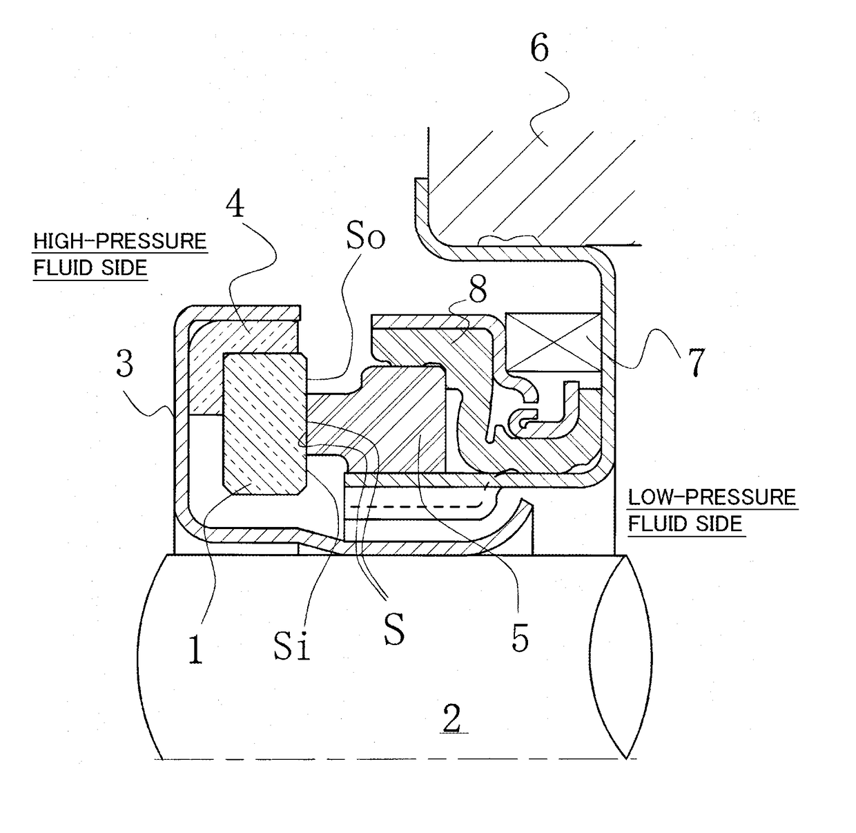
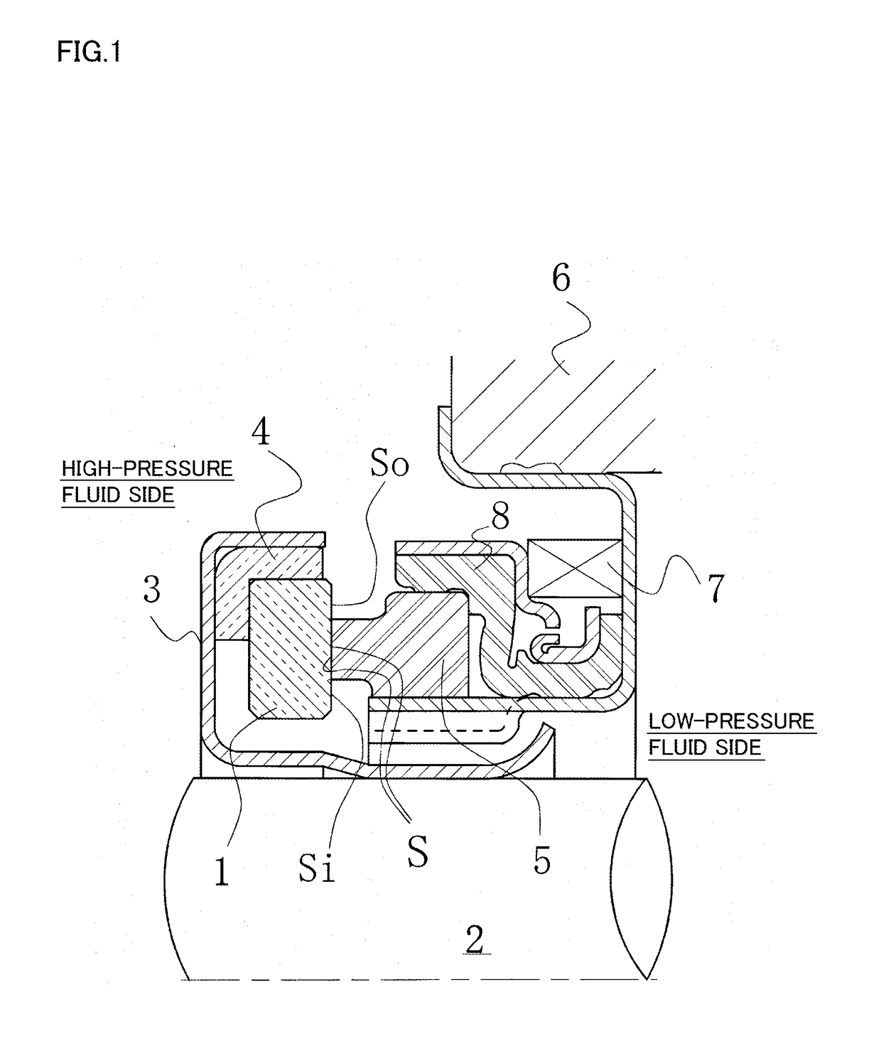
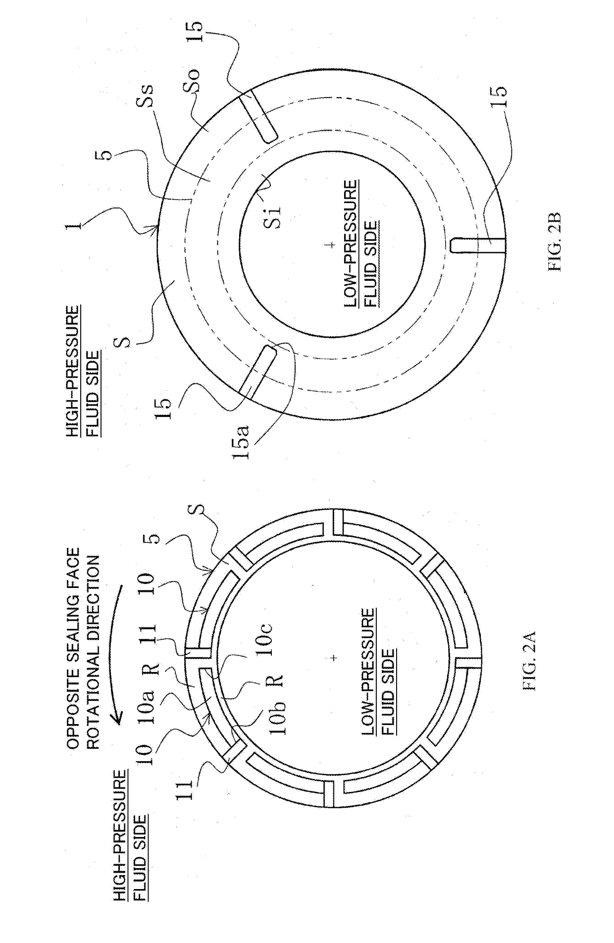
[0035]With reference to FIG. 1 and FIGS. 2A and 2B, a slide component according to a first embodiment of the present invention will be described.

[0036]In the following embodiment, a mechanical seal, an example of the slide component, will be described as an example. The outer peripheral side of slide parts constituting the mechanical seal is described as the high-pressure fluid side (sealed fluid side), and the inner peripheral side as the low-pressure fluid side (atmosphere side). However, the present invention is not limited to this, and is also applicable to a case where the high-pressure fluid side and the low-pressure fluid side are reversed.

[0037]FIG. 1 is a vertical cross-sectional view showing an example of the mechanical seal, which is an inside mechanical seal in a form of sealing a sealed fluid on the high-pressure fluid side tending to leak from the outer periphery of sealing faces toward the inner periphery. The mechanical seal is provided, on the side of a rotating sha...

second embodiment

[0065]With reference to FIGS. 3A and 3B, a slide component according to a second embodiment of the present invention will be described.

[0066]The second embodiment is different from the first embodiment in that fluid circulation grooves 20 are added in a sealing face S of a stationary-side seal ring 5, but the other basic configuration is the same as that in the first embodiment. The same numerals and symbols as those in the first embodiment denote the same members, and redundant descriptions will be omitted.

[0067]In FIG. 3A, in the sealing face S of the stationary-side seal ring 5, four fluid circulation grooves 20 communicating with the high-pressure fluid side and separated from the low-pressure fluid side by a smooth portion R (sometimes referred to as a “land portion” in the present invention) on the sealing face are evenly spaced circumferentially.

[0068]The number of the fluid circulation grooves 20 is not limited to four. It is only necessary to provide at least one. Further, ...

third embodiment

[0088]With reference to FIGS. 4A and 4B, a slide component according to a third embodiment of the present invention will be described.

[0089]The third embodiment is different from the second embodiment in that positive pressure generation mechanisms 25 are added on a sealing face S of a stationary-side seal ring 5, but the other basic configuration is the same as that in the second embodiment. The same numerals and symbols as those in the second embodiment denote the same members, and redundant descriptions will be omitted.

[0090]In FIG. 4A, the positive pressure generation mechanisms 25 each having a positive pressure generation groove 25a shallower than fluid circulation grooves 20 are provided in portions enclosed by the fluid circulation grooves 20 in the sealing face S of the stationary-side seal ring 5 and the high-pressure fluid side.

[0091]The positive pressure generation mechanisms 25 are intended to generate positive pressure (dynamic pressure), thereby increasing a fluid fil...


PUM


Abstract

In an embodiment, a slide component includes one slide part 5 provided, on a low-pressure side of a sealing face thereof, with a negative pressure generation mechanism 10 including a negative pressure generation groove 10. The negative pressure generation groove 10a communicates with a high-pressure fluid side and is separated from a low-pressure fluid side by a land portion R. Another slide part 1 is provided, in a sealing face thereof, with at least one interference groove 15 communicating with the high-pressure fluid side for producing pressure variations in a fluid in the negative pressure generation groove 10a. The at least one interference groove 15 has an end 15a on an inside-diameter side extending to a position to radially overlap the negative pressure generation groove 10a.

Description

TECHNICAL FIELD[0001]The present invention relates to slide components suitable for, for example, mechanical seals, bearings, and other slide units, and in particular, relates to slide components such as seal rings or bearings that require friction reduction by interposing a fluid between sealing faces as well as prevention of fluid leakage from the sealing faces.BACKGROUND ART[0002]A mechanical seal, an example of a slide component, is evaluated for its performance by a leakage rate, a wear rate, and a torque. In conventional arts, by optimizing the seal material and the sealing face roughness of mechanical seals, their performance is increased to achieve low leakage, long life, and low torque. However, due to growing awareness of environmental problems in recent years, a further improvement in the performance of mechanical seals has been demanded, for which technology development beyond the limits of the conventional arts has been required.[0003]In that context, the present invent...

Claims


Application Information

Patent Timeline
Patent Type & Authority Applications(United States)
IPC IPC(8): F16J15/40F16J15/34
CPCF16J15/34F16J15/40F16J15/3412F16J15/342
Inventor ITADANI, MASATOSHISUNAGAWA, KAZUMASATOKUNAGA, YUICHIROINOUE, HIDEYUKIHOSOE, TAKESHIYAMAKAWA, RYOMANEGISHI, YUTAKIRYU, KENJICHIBA, KEIICHIYOSHINO, AKIRAKUBOTA, HIROSHI
Owner EAGLE INDS
Why Eureka
Try Eureka