Zoom lens and image pickup apparatus including the same

a pickup apparatus and zoom lens technology, applied in the field of zoom lens and image pickup apparatus, can solve the problems of difficult to obtain good optical performance over the entire object distance, increase the variation of focusing angle, etc., and achieve the effect of small image magnification change and high optical performan

Active Publication Date: 2017-08-24
CANON KK
View PDF13 Cites 5 Cited by
  • Summary
  • Abstract
  • Description
  • Claims
  • Application Information

AI Technical Summary

Benefits of technology

[0013]It is an object of the present invention to provide a zoom lens, which includes a small focusing lens unit and has a small image magnification change during focusing, thereby being small as the entire system and having high optical performance.

Problems solved by technology

Therefore, the aberration variations during focusing are increased, and hence it becomes difficult to obtain good optical performance over the entire object distance from a long distance to a short distance.

Method used


Image

  • Zoom lens and image pickup apparatus including the same
  • Zoom lens and image pickup apparatus including the same
  • Zoom lens and image pickup apparatus including the same

Examples


embodiment 1

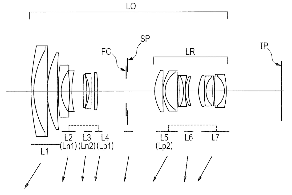
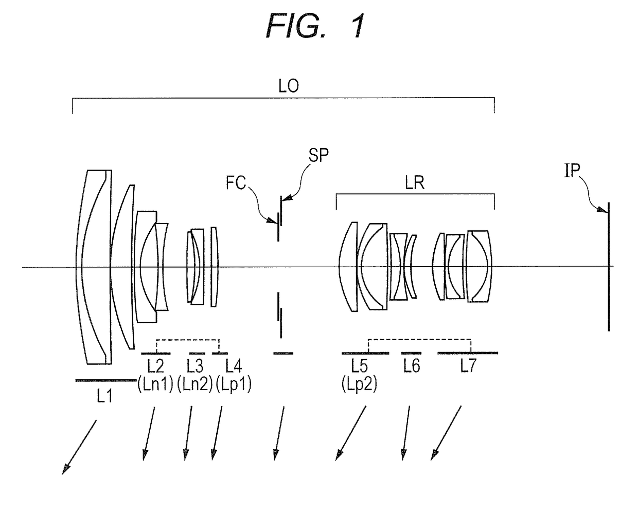
[0058]In Embodiment 1, a lens unit L1 having a positive refractive power is arranged on the object side of the lens unit Ln1, and the rear lens group LR consists of a lens unit L5 having a positive refractive power, a lens unit L6 having a weak negative refractive power, and a lens unit L7 having a negative refractive power, which are arranged in order from the object side to the image side. The lens unit L5 has the strongest refractive power among lens units having positive refractive powers.

embodiment 2

[0059]In Embodiment 2, a lens unit L1 having a positive refractive power is arranged on the object side of the lens unit Ln1, and the rear lens group LR consists of a lens unit L5 having a positive refractive power, a lens unit L6 having a negative refractive power, and a lens unit L7 having a positive refractive power, which are arranged in order from the object side to the image side. The lens unit L5 has the strongest refractive power among lens units having positive refractive powers.

embodiment 3

[0060]In Embodiment 3, a lens unit L1 having a positive refractive power is arranged on the object side of the lens unit Ln1, and the rear lens group LR consists of a lens unit L5 having a positive refractive power, a lens unit L6 having a positive refractive power, a lens unit L7 having a negative refractive power, and a lens unit L8 having a weak negative refractive power, which are arranged in order from the object side to the image side. The lens unit L6 has the strongest refractive power among lens units having positive refractive powers.


PUM


Abstract

Provided is a zoom lens including: a lens unit Ln1 having a negative refractive power; a lens unit Ln2 having a negative refractive power; a lens unit Lp1 having a positive refractive power; and a rear lens group including one or more lens units, the lens unit Ln1, the lens unit Ln2, the lens unit Lp1, and the rear lens group being successively arranged in order from an object side to an image side, in which the lens unit Ln1 and the lens unit Lp1 are moved along the same locus during zooming, and in which the lens unit Ln2 is moved toward the object side during focusing from infinity to proximity.

Description

BACKGROUND OF THE INVENTION[0001]Field of the Invention[0002]The present invention relates to a zoom lens and an image pickup apparatus including the same, and is suitable to an image pickup optical system used in an image pickup apparatus, e.g., a digital camera, a video camera, a TV camera, a monitoring camera, or a silver-halide film camera.[0003]Description of the Related Art[0004]As an image pickup optical system used in an image pickup apparatus, there is demanded an image pickup optical system, which is capable of moving a focus lens at high speed and with high accuracy during focusing, and which is reduced in image magnification change during focusing.[0005]A lens unit arranged closest to an object side in the image pickup optical system tends to be increased in size and weight. Therefore, there is known a zoom lens, which uses, for focusing, a lens unit arranged on an image side of the lens unit arranged closest to the object side.[0006]In Japanese Patent Application Laid-O...

Claims


Application Information

Patent Timeline
Patent Type & Authority Applications(United States)
IPC IPC(8): G02B15/20G02B15/177G02B7/10
CPCG02B15/20G02B15/177G02B7/10G02B15/1445G02B15/1451G02B15/00
Inventor SUGITA, SHIGENOBU
Owner CANON KK
Why Eureka
Try Eureka