Fixation device and image formation apparatus
a technology of fixation device and image formation apparatus, which is applied in the direction of electrographic process apparatus, instruments, optics, etc., can solve the problems of deformation large pressure difference between the regions of the fixation belt corresponding to each other,
- Summary
- Abstract
- Description
- Claims
- Application Information
AI Technical Summary
Benefits of technology
Problems solved by technology
Method used
Image
Examples
embodiment 1
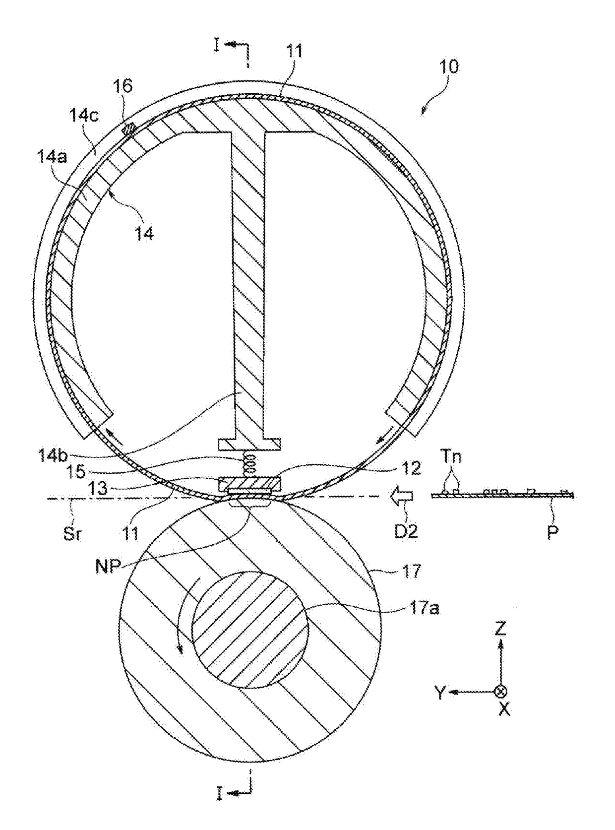
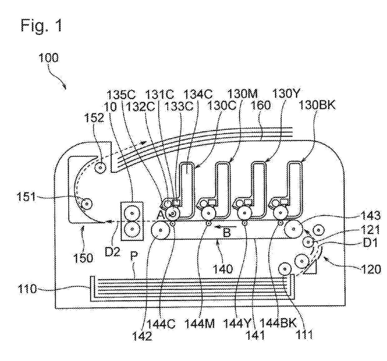
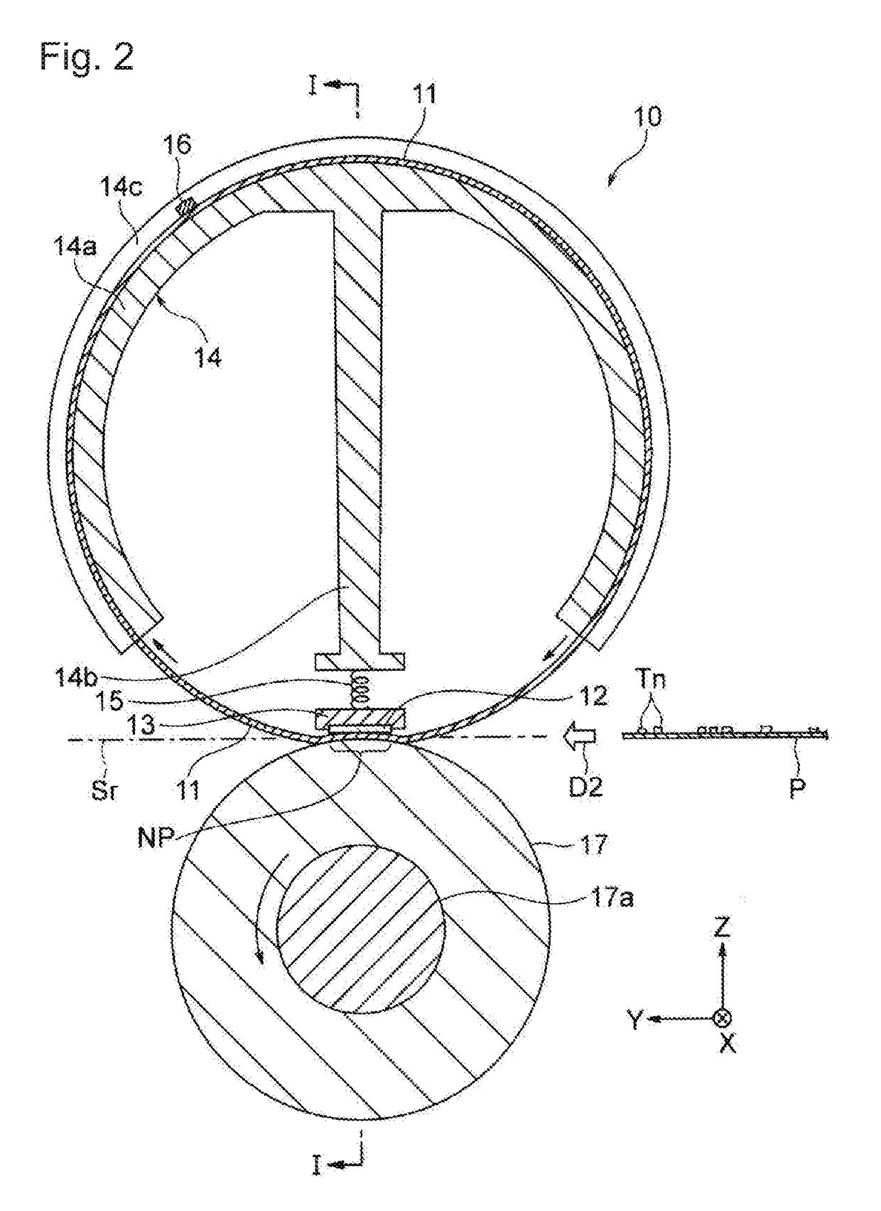
[0024]FIG. 1 is a vertical cross-sectional diagram schematically illustrating an example configuration of an image formation apparatus including a fixation device according to Embodiment 1. Image formation apparatus 100 illustrated in FIG. 1 includes fixation device 10 according to Embodiment 1, and its examples include a color printer which employs electrophotography and forms a color image. Note that fixation device 10 according to Embodiment 1 can be provided to a single-color printer which forms a single-color image, such as a monochrome printer. Also, fixation device 10 can be provided to other image formation apparatuses such as a copier, a facsimile device, and a multifunction printer (MFP). Note that the dotted arrows in FIG. 1 indicate conveyance directions of printing medium (recording medium) P to be conveyed.
[0025]As main components, image formation apparatus 100 includes: feed cassette 110 which retains (stores) printing medium P being a sheet-shaped medium such as a pa...
embodiment 2
[0071]FIG. 7A is a cross-sectional diagram illustrating an example configuration of a fixation device according to Embodiment 2, and FIG. 7B is a cross-sectional diagram illustrating a support member in the fixation device. In FIGS. 7A and 7B, parts having functions the same as or corresponding to those in FIGS. 3A and 3B are assigned the same reference numerals used in FIGS. 3A and 3B. Note that although FIG. 7A does not illustrate printing medium P, but a cross section corresponding to the cross section depicted in FIG. 3A, printing medium P passes on reference passage surface Sr. Hereinbelow, Embodiment 2 is described mainly focusing on the differences from Embodiment 1. Various examples described in Embodiment 1 can be applied to Embodiment 2.
[0072]Fixation device 10 according to Embodiment 1 has one step at each of both end portions in the width direction of heater support member 13. On the other hand, fixation device 70 according to Embodiment 2 illustrated in FIG. 7A has a ta...
embodiment 3
[0076]FIG. 8 is a cross-sectional diagram illustrating an example configuration of a fixation device according to Embodiment 3. In FIG. 8, parts having functions the same as or corresponding to those in FIG. 3A are assigned the same reference numerals used in FIG. 3A. Note that although FIG. 8 does not illustrate printing medium P, but a cross section corresponding to the cross section depicted in FIG. 3A, printing medium P passes on reference passage surface Sr. Hereinbelow, Embodiment 3 is described mainly focusing on the differences from Embodiment 1. Various examples described in Embodiments 1 and 2 can be applied to Embodiment 3.
[0077]As illustrated in FIG. 3A, fixation device 10 according to Embodiment 1 defines first distance Da and second distance Db to be compared with the reference set to each end portion P0 in the width direction of printing medium P, and reduces the pressure difference at the fixation belt attributed to end portions P0 in the width direction of printing ...
PUM
 Abstract
Description
Claims
Application Information
 - R&D
- Intellectual Property
- Life Sciences
- Materials
- Tech Scout
- Unparalleled Data Quality
- Higher Quality Content
- 60% Fewer Hallucinations
Browse by: Latest US Patents, China's latest patents, Technical Efficacy Thesaurus, Application Domain, Technology Topic, Popular Technical Reports.
© 2025 PatSnap. All rights reserved.Legal|Privacy policy|Modern Slavery Act Transparency Statement|Sitemap|About US| Contact US: help@patsnap.com


