
Electric power converter

a technology of electric power converter and power supply, which is applied in the direction of casing/cabinet/drawer details, electric apparatus casing/cabinet/drawer, battery/cell propulsion, etc., can solve the problems of difficult to fix at the desired fixing strength, the second electronic circuit board is likely to be deformed, and the number of fixing points cannot be increased. , to achieve the effect of enhancing the fixing strength of a plurality and increasing the number of fixing points

Active Publication Date: 2019-12-31
DENSO CORP
View PDF14 Cites 2 Cited by
  • Summary
  • Abstract
  • Description
  • Claims
  • Application Information

AI Technical Summary

Benefits of technology

This configuration increases the number of fixing points, preventing concentration at the circuit board corners and ensuring the boards can withstand vehicle vibrations, while also providing magnetic shielding and thermal management.

Problems solved by technology

Accordingly, the second electronic circuit board cannot be fixed to the container with an increased number of fixing points due to interference by the first electronic circuit board.
Accordingly, the second electronic circuit board is likely to be deformed by external force and is difficult to fix at a desired fixing strength at which the second electronic circuit board could withstand vibrations from the vehicle during running.

Method used


Image

  • Electric power converter
  • Electric power converter
  • Electric power converter

Examples


first embodiment

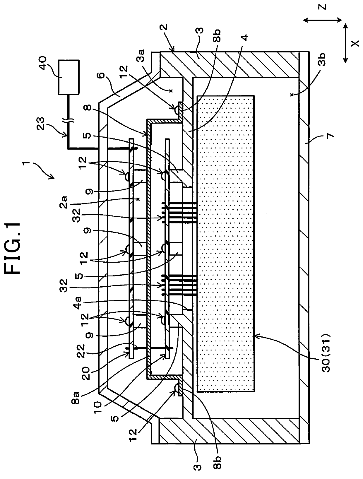
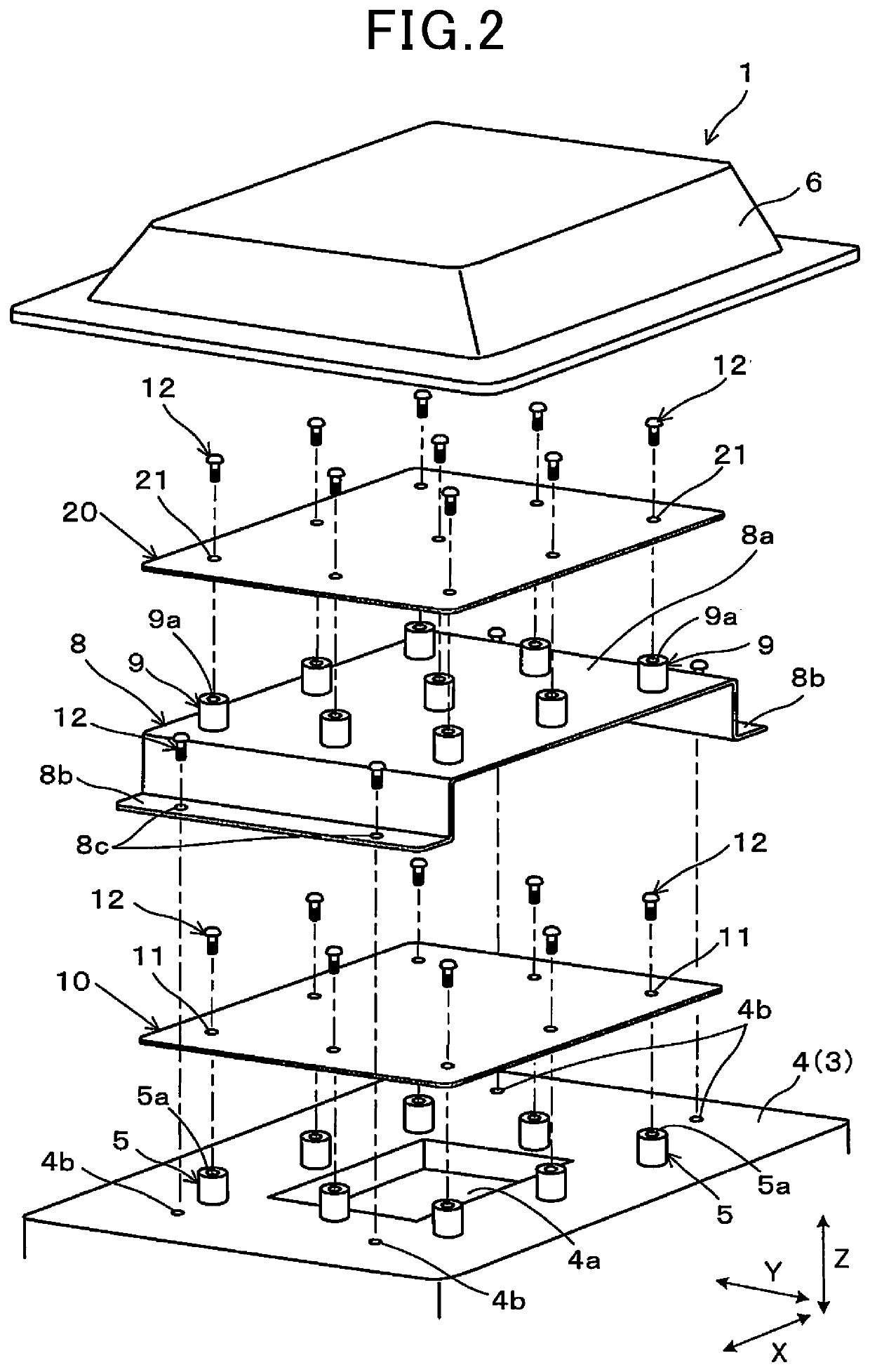
[0022]As illustrated in FIG. 1, an electric power converter 1 in a first embodiment includes a plurality of elements such as a first electronic circuit board 10, a second electronic circuit board 20, and a semiconductor module 30. The plurality of elements is contained in an internal space defined by a container 2. The electric power converter 1 is mounted in an electric automobile or a hybrid automobile and is used as an inverter that converts direct-current power into alternating-current power necessary for driving a drive motor, for example.

[0023]The container 2 has a case 3, a cover 6 that covers an opening 3a in the case 3, and a cover 7 that covers an opening 3b in the case 3. The case 3 includes a partition wall 4 that partitions an internal space in the third direction Z. The partition wall 4 has a plurality of boss portions (first fixing portion) 5 that extends toward the first electronic circuit board 10 to fix the first electronic circuit board 10. Each of the boss portio...

second embodiment

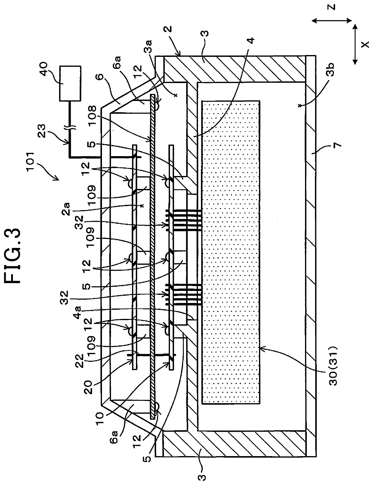
[0045]An electric power converter 101 in a second embodiment is different from the electric power converter 1 in the first embodiment in the fixing structure of a second electronic circuit board 20. In other respects, the second embodiment is configured in the same manner as the first embodiment. Therefore, only the elements related to the fixing structure of the second electronic circuit board 20 will be described below with reference to FIGS. 3 and 4, and descriptions of the other elements will be omitted. In these drawings, the same elements as those illustrated in FIGS. 1 and 2 are given the same reference signs as those in FIGS. 1 and 2.

[0046]As illustrated in FIG. 3, an inter-board plate 108 is interposed as an interposition member between a first electronic circuit board 10 and the second electronic circuit board 20. The inter-board plate 108 is rectangular in planar view and is configured to exceed both the first electronic circuit board 10 and the second electronic circuit ...


PUM


Abstract

An electric power converter includes a semiconductor module, a first electronic circuit board, a second electronic circuit board, and a container that contains the first electronic circuit board and the second electronic circuit board. The container has a first fixing portion to which the first electronic circuit board is fixed and a second fixing portion to which the second electronic circuit board is fixed. The electric power converter is configured such that the second electronic circuit board does not intervene between the first fixing portion of the container and the first electronic circuit board in the board thickness direction and the first electronic circuit board does not intervene between the second fixing portion of the container and the second electronic circuit board in the board thickness direction.

Description

CROSS-REFERENCE TO RELATED APPLICATION[0001]This application is the U.S. national phase of International Application No. PCT / JP2017 / 001909 filed Jan. 20, 2017 which designated the U.S. and claims priority to Japanese Patent Application No. 2016-21061 filed Feb. 5, 2016, the contents of which are incorporated herein by reference.TECHNICAL FIELD[0002]The present disclosure relates to an electric power converter including a plurality of electronic circuit boards.BACKGROUND ART[0003]A vehicle such as an electric automobile or a hybrid automobile is equipped with an electric power converter that performs power conversion between direct-current power and alternating-current power. For example, PTL 1 listed below discloses an electric power converter that includes a semiconductor module with a built-in semiconductor element and a plurality of electronic circuit boards. The plurality of electronic circuit boards includes a first electronic circuit board for high-voltage system and a second ...

Claims


Application Information

Patent Timeline
Patent Type & Authority Patents(United States)
IPC IPC(8): H05K7/02H05K7/04H05K7/14B60L50/51H02M7/48H02M7/00H05K5/02
CPCH05K7/1432H02M7/48H02M7/003B60L50/51H05K7/1417H05K5/0239H05K2201/042H05K1/144H05K7/14H05K2201/2036Y02T10/70H05K2201/10371H05K5/03H05K9/0026H05K7/14322
Inventor KOGURE, SHINTARO
Owner DENSO CORP
Learn More