Piezoelectric vibrator element, and piezoelectric vibrator

a piezoelectric vibrator and piezoelectric technology, applied in piezoelectric/electrostrictive/magnetostrictive devices, piezoelectric/electrostrictive/magnetostriction machines, mechanical vibration separation, etc., can solve the problems of inability to achieve miniaturization and decrease in the distance to the fixation part via the base, so as to achieve the effect of reducing the distance to the fixation part and suppressing the leakage of vibration

Active Publication Date: 2017-08-24
SII CRYSTAL TECH
View PDF0 Cites 1 Cited by
  • Summary
  • Abstract
  • Description
  • Claims
  • Application Information

AI Technical Summary

Benefits of technology

[0012]The invention has an object of miniaturizing the piezoelectric vibrator element, and at the same time, suppressing the vibration leakage.
[0018]According to the invention, it is possible to miniaturize the piezoelectric vibrator element, and at the same time, the vibration leakage can be suppressed.

Problems solved by technology

However, the sum of the lengths of the base and the vibrating arm corresponds to the total length of the piezoelectric vibrator element, and if the base is shortened for the miniaturization, the distance to the fixation part via the base decreases to weaken the suppression effect of the vibration leakage, and if, in contrast, the length of the base is increased, the miniaturization cannot be achieved.

Method used


Image

  • Piezoelectric vibrator element, and piezoelectric vibrator
  • Piezoelectric vibrator element, and piezoelectric vibrator
  • Piezoelectric vibrator element, and piezoelectric vibrator

Examples


embodiment

(1) OUTLINE OF EMBODIMENT

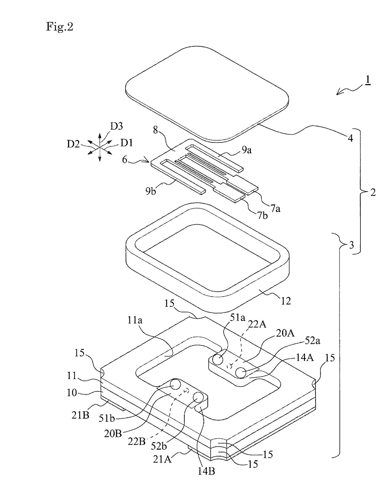
[0024]The piezoelectric vibrator element 6 according to the present embodiment is a piezoelectric vibrator element shaped like a tuning fork provided with a pair of vibrating arm parts 7 extending from a base 8, and support arm parts 9 extending from the base 8 on both outer sides of the vibrating arm parts 7 in parallel to the vibrating arm parts 7. In the longitudinal direction of the pair of vibrating arm parts 7, groove parts 72 each having a constant width are formed on the principal surfaces (the reverse and obverse surfaces) of each of the vibrating arm parts 7.

[0025]On the side surfaces and principal surfaces constituting the outer peripheral surfaces of the vibrating arm parts 7, and the inside of the groove parts 72, there are formed excitation electrodes 91, 92 of two systems different from each other functioning as a first excitation electrode and a second excitation electrode.

[0026]In the piezoelectric vibrator element 6 according to the present...

first embodiment

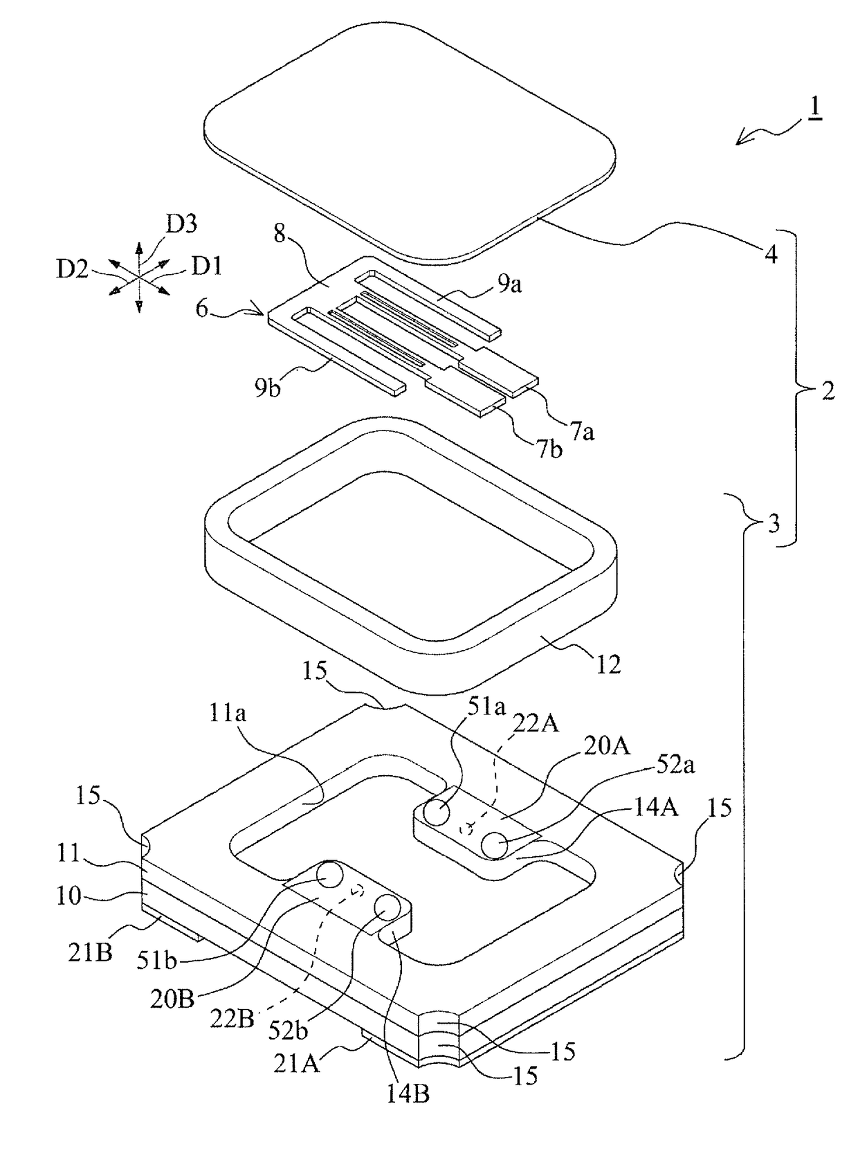
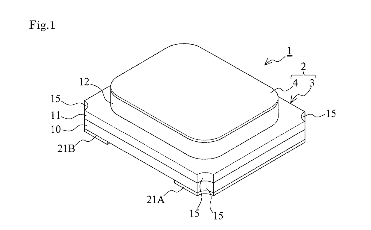
[0033]FIG. 1 is an exterior perspective view of the piezoelectric vibrator equipped with the piezoelectric vibrator element according to the first embodiment. FIG. 2 is an exploded perspective view of the piezoelectric vibrator according to the first embodiment.

[0034]As shown in FIGS. 1 and 2, the piezoelectric vibrator 1 according to the present embodiment is formed as a surface-mounted vibrator of a ceramic package type provided with a package 2 incorporating a cavity C airtightly sealed, and a piezoelectric vibrator element 6 housed in the cavity C.

[0035]It should be noted that since the piezoelectric vibrator 1 according to the present embodiment has a bilaterally symmetrical structure, in the description, the both parts symmetrically disposed will be denoted by the same numeric characters, and in order to distinguish the both parts from each other, discriminators a, A are attached to one of the parts and discriminators b, B are attached to the other of the parts in such a manne...


PUM


Abstract

The piezoelectric vibrator element is miniaturized, and at the same time, the vibration leakage is suppressed. The piezoelectric vibrator element is formed so that the total length L1 of the piezoelectric vibrator element, the length L2 of the base, the width L3 of the connection part, the length L4 of the support arm part fulfill all of the following conditions A through C, Condition A: 0.1≦L2 / L1≦0.2, Condition B: 0.4≦L3 / L2≦0.6, Condition C: L4 / L1≧0.7. While the miniaturization is realized by shortening the base due to the condition A, the distance via the base can be elongated due to the condition B. Further, by increasing the length of the support arm parts due to the condition C, it is possible to increase the total mass of the path transmitting the vibration to absorb the vibration to thereby further suppress the vibration leakage.

Description

RELATED APPLICATIONS[0001]This application claims priority under 35 U.S.C. §119 to Japanese Patent Application No. 2016-031988 filed on Feb. 23, 2016, the entire content of which is hereby incorporated by reference.BACKGROUND OF THE INVENTION[0002]1. Technical Field[0003]The present invention relates to a piezoelectric vibrator element and a piezoelectric vibrator, and in detail to an excitation electrode for exciting a vibrating arm part.[0004]2. Related Art[0005]For example, in the electronic apparatus such as a cellular phone or a portable information terminal, a piezoelectric vibrator using a quartz crystal or the like is used as a device used for a clock time source, a timing source for a control signal and so on, a reference signal source, and so on. As a piezoelectric vibrator of this kind, there has been known a device having a piezoelectric vibrator element hermetically encapsulated in a cavity formed of a package and a lid member as shown in JP-A-2015-97364 (Document 1).[0...

Claims


Application Information

Patent Timeline
Patent Type & Authority Applications(United States)
IPC IPC(8): H02N2/00H01L41/187B06B1/06H01L41/09
CPCH02N2/0015H01L41/0933H01L41/187B06B1/0603H03H9/02157H03H9/0509H03H9/215H03H9/1014H03H9/21H10N30/853H10N30/2041
Inventor ICHIMURA, NAOYA
Owner SII CRYSTAL TECH
Why Eureka
Try Eureka