Working vehicle

a technology for working implements and vehicles, applied in agricultural machines, adjusting devices, agricultural tools and machines, etc., can solve the problems of difficult connection of working implements to quick hitches, working implements that cannot be inclined to appropriately locate engagement devices, etc., and achieve the effect of easy connection

Active Publication Date: 2017-08-31
YANMAR POWER TECHNOLOGY CO LTD
View PDF0 Cites 2 Cited by
  • Summary
  • Abstract
  • Description
  • Claims
  • Application Information

AI Technical Summary

Benefits of technology

[0017]Therefore, due to the connection assist frame mounted on the working implement, the working implement can easily be connected to the quick hitch even if the working implement includes only a connection device insufficient in facility for its connection to the quick hitch. Further, due to the automatic connection of the coupling of the quick hitch to the PTO stub axle of the connection assist frame, an operator does not have to be nervous about connection of the connection shaft extended from the PTO shaft to the drive shaft of the working implement if only the operator takes care of operating the linkage to connect the quick hitch to the connection assist frame on the working implement.
[0018]As mentioned above, the working vehicle of the present invention is advantageous in facility for connecting the quick hitch to the working implement.

Problems solved by technology

However, there are some kinds of working implements that cannot be inclined to appropriately locate their engagement devices.
If the working vehicle needs such a kind of working implement to be connected to its vehicle body via the quick hitch, it may be difficult to connect the working implement to the quick hitch.

Method used


Image

  • Working vehicle
  • Working vehicle
  • Working vehicle

Examples


Embodiment Construction

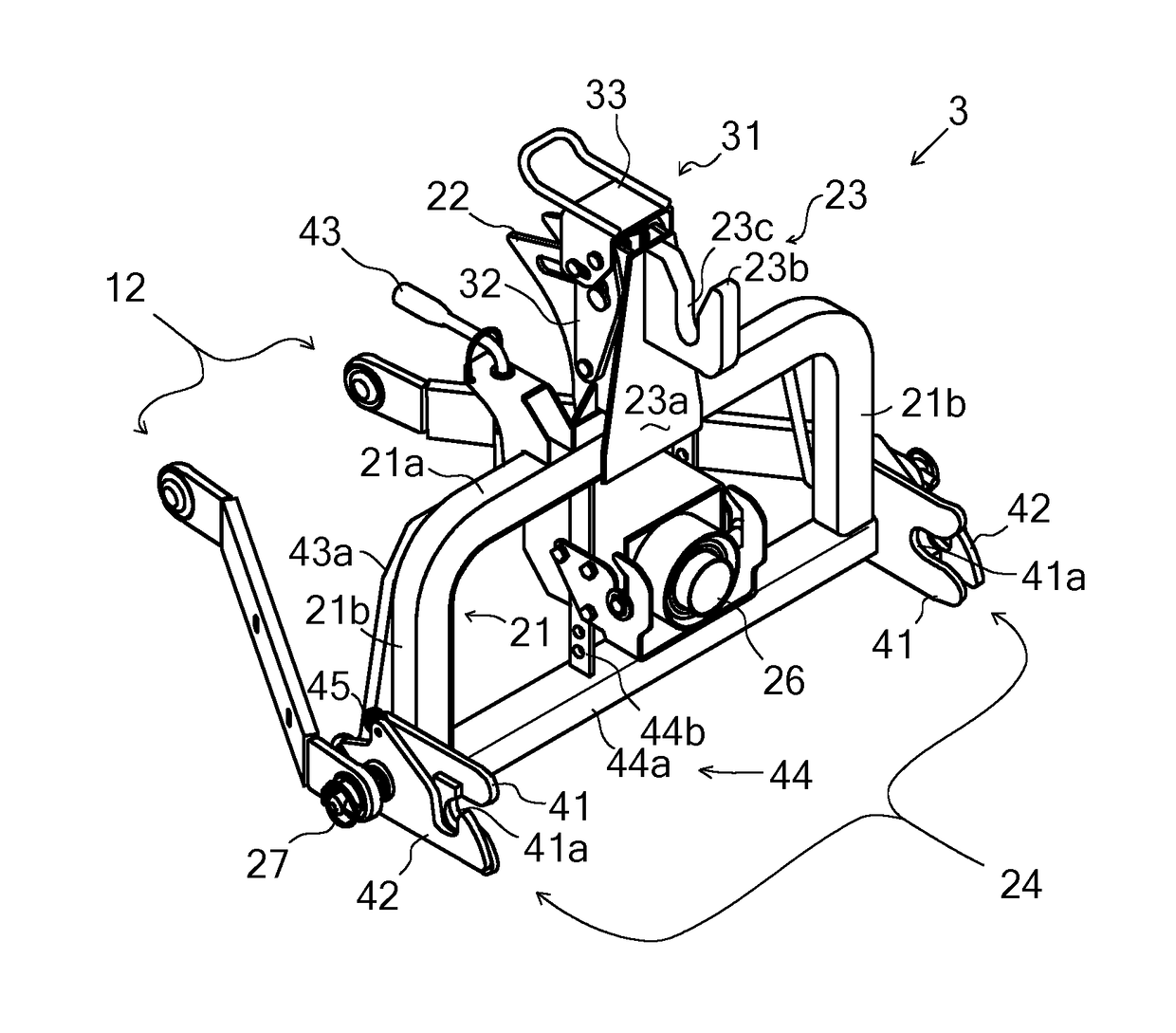
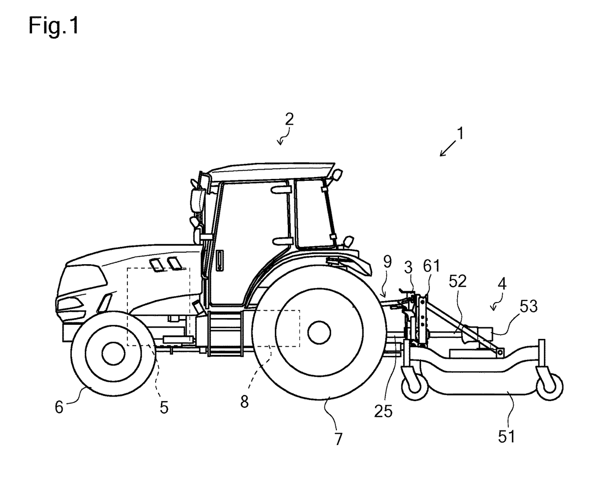
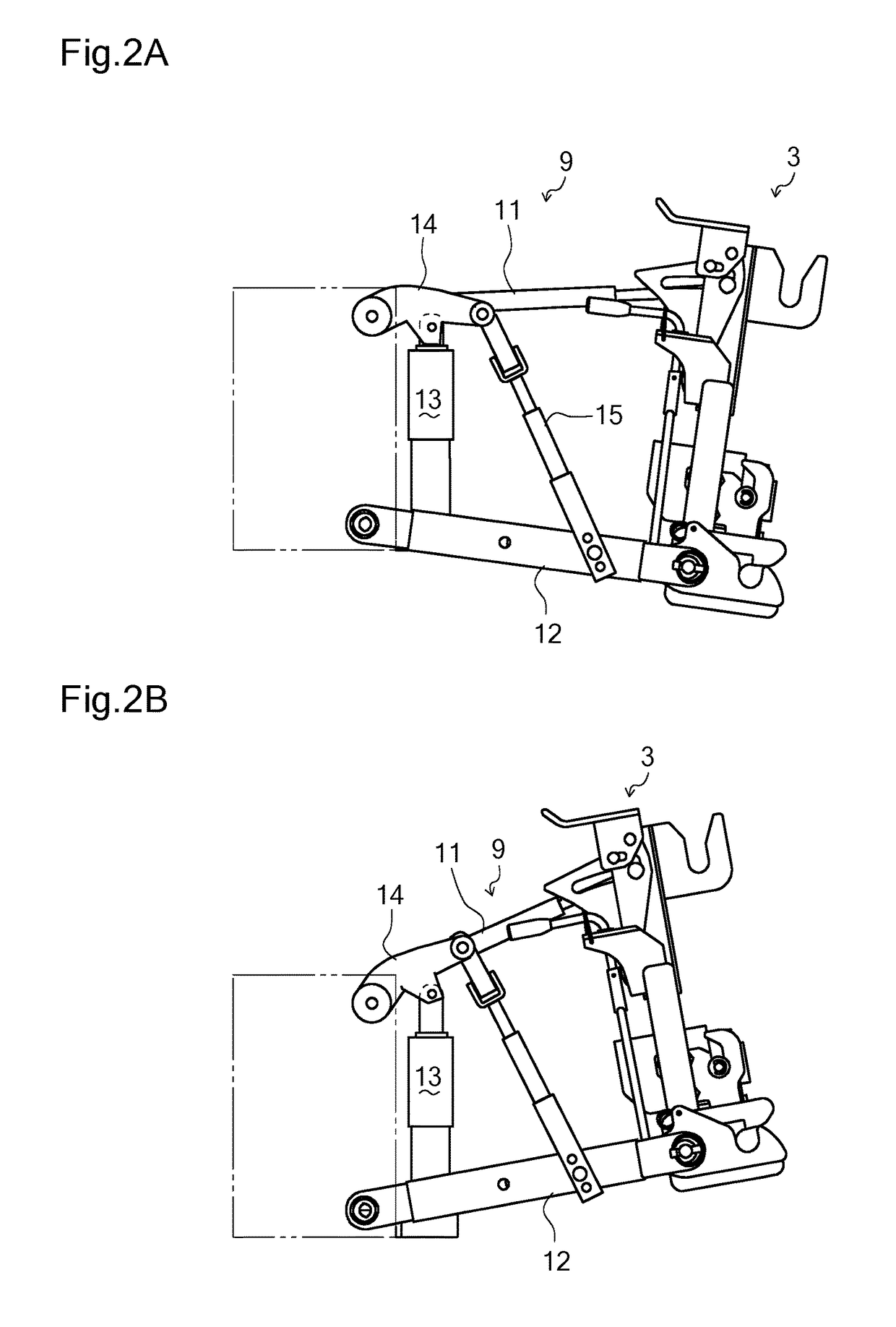
[0033]An entire configuration of a working vehicle 1 according to an embodiment of the invention will be described with reference to FIG. 1 and other drawings. In this embodiment, a tractor serves as working vehicle 1, however, working vehicle 1 is not limited to the tractor.

[0034]Working vehicle 1 includes a vehicle body 2, and a working implement 4 connected to a rear portion of vehicle body 2 via a quick hitch 3. Vehicle body 2 is provided with an engine 5, front wheels 6 and rear wheels 7, so that working vehicle 1 travels with front wheels 6 and rear wheels 7 driven by power from engine 5, and working implement 4 works during the travel of working vehicle 1. Vehicle body 2 is provided at a rear portion thereof with a transmission casing 8 for transmitting the power from engine 5 to front wheels 6 and rear wheels 7. Further, transmission casing 8 defining the rear portion of vehicle body 2 is provided at a rear portion thereof with a PTO shaft (not shown), which transmits the po...


PUM


Abstract

A working vehicle comprises a vehicle body, a quick hitch, a working implement connected to the vehicle body via the quick hitch, and a linkage interposed between the quick hitch and the vehicle body. The linkage is movable to raise and lower the quick hitch so as to locate the quick hitch at an optional height. The quick hitch can be inclined to a certain degree in a pitching direction of the vehicle body at the optional height defined by the linkage.

Description

BACKGROUND OF THE INVENTION[0001]Field of the Invention[0002]The present invention relates to a working vehicle in which a working implement is connected to a vehicle body via a quick hitch.[0003]Related Art[0004]A tractor disclosed by JP 2011-50262 A has a rotary cultivator connected to the vehicle body via a quick hitch provided on a rear portion of the vehicle body. In this regard, the tractor is provided with a three-point linkage at the rear portion of the vehicle body. The three-point linkage includes a top link and a pair of right and left lower links. The lower links are able to rotate upward and downward by activating respective hydraulic lift cylinders. The top link is disposed upward from a lateral central position between the right and left lower links. The quick hitch is attached to the three-point linkage so as to connect a rear end of the top link to rear ends of the right and left lower links.[0005]The quick hitch is provided at a laterally central top portion thereo...

Claims


Application Information

Patent Timeline
Patent Type & Authority Applications(United States)
IPC IPC(8): A01B59/043A01B71/06A01B63/14
CPCA01B59/043A01B71/063A01B63/14A01B59/062
Inventor HYDER, JARROD
Owner YANMAR POWER TECHNOLOGY CO LTD
Why Eureka
Try Eureka