Method and arrangement for transferring a heavy work machine on a sloping base

a technology of heavy work and sloping base, which is applied in mechanical machines/dredgers, transportation items, braking systems, etc., can solve the problems of difficult to achieve the necessary braking power the problem of difficult to achieve braking effect, and the insufficient brakes of the transfer vehicle, etc., to achieve the effect of improving the adhesion of towing

Active Publication Date: 2017-09-07
SLEIPNER FINLAND
View PDF3 Cites 5 Cited by
  • Summary
  • Abstract
  • Description
  • Claims
  • Application Information

AI Technical Summary

Benefits of technology

[0037]Alternatively, the arm can form the support plane. Such an implementation is particularly suitable for transfer trailers that are towed by lighter transfer vehicles, in which case, by pressing the arm by the set of booms of the work machine, additional, mass is transferred to the transfer vehicle, in order to improve towing adhesion.

Problems solved by technology

The transfer of heavy excavators equipped with crawler tracks, for example, in mines and quarries, is problematic.
However, a problem in such, a solution is the great mass of an excavator when moving it on a sloping base.
When correctly dimensioned, the power of the transfer vehicle will be sufficient for the transfer; but braking effect often becomes a problem.
The brakes of the transfer vehicle will then be insufficient to produce the necessary braking power, or at least will operate at the extreme limit of their capacity.
In addition, a problem in such transfers is the slipperiness of the sloping base, for example, in winter or in rain, when an excavator or work machine with a great mass can push the transfer vehicle downhill in front of it, causing a great hazard.
The base material too can be slippery.
In addition to excavators, the problem can also appear in connection with other heavy work machines equipped with a work boom.

Method used


Image

  • Method and arrangement for transferring a heavy work machine on a sloping base
  • Method and arrangement for transferring a heavy work machine on a sloping base
  • Method and arrangement for transferring a heavy work machine on a sloping base

Examples


second embodiment

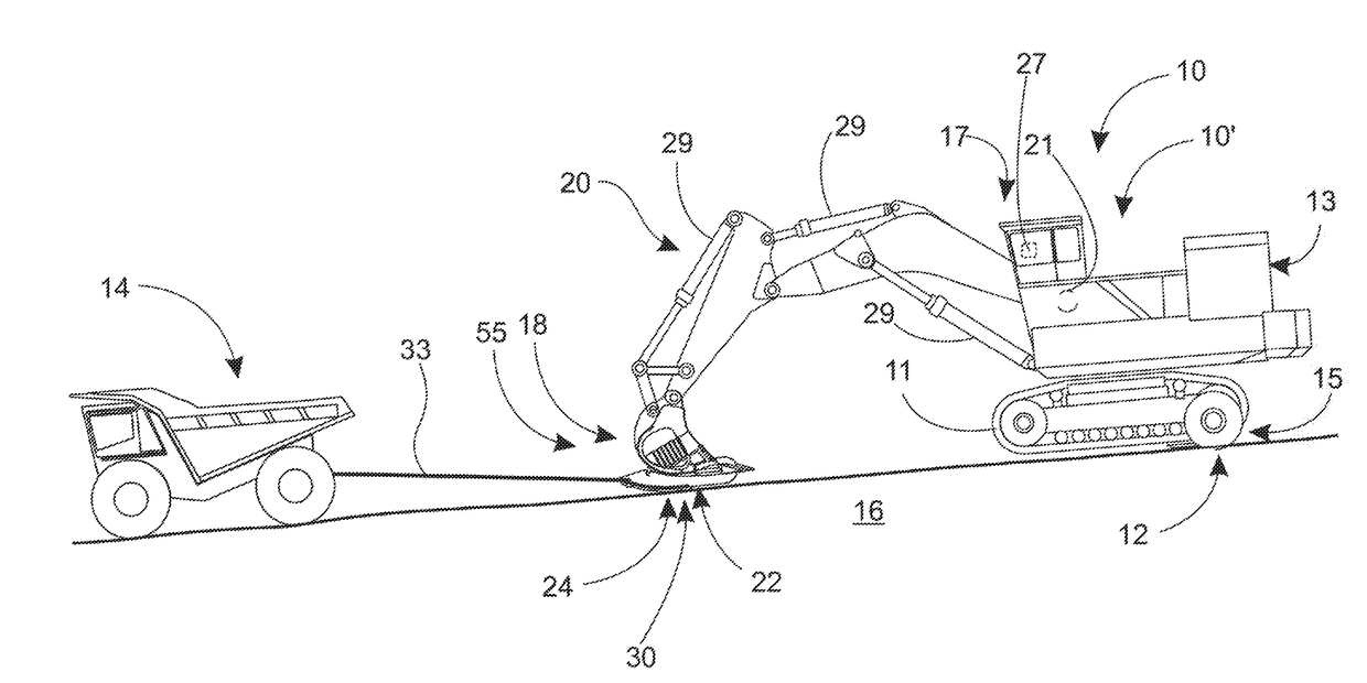
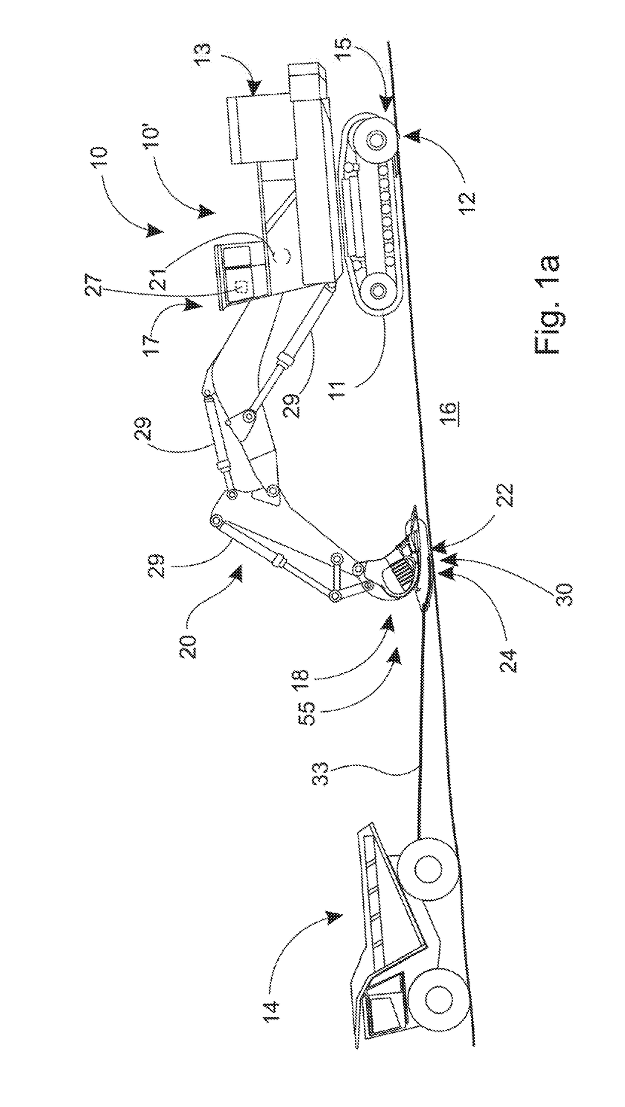
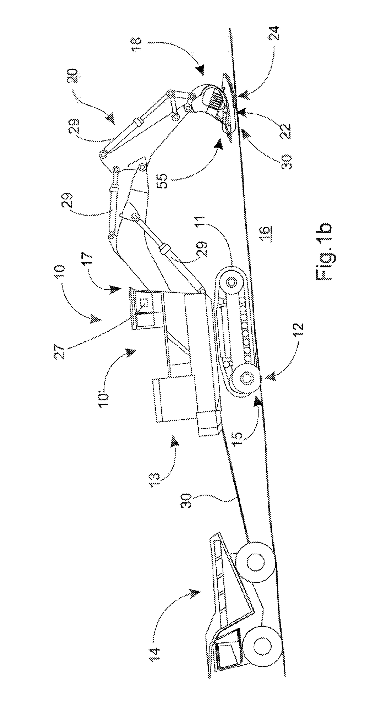
[0054]FIG. 1c shows the arrangement, is which the work machine 10 is an excavator equipped with a dipper shovel 18′. When using a dipper shovel 18′, the brake means 30 differ slightly in construction from the embodiment of FIGS. 1a and 1b, mainly due to the operating attitude of the dipper shovel 18′. The dipper shovel 18′ differs in construction from the bucket 18 of the embodiment of FIGS. 1a and 1b in that the dipper shovel 18′ consists of a body part 50 and a jaw part 52 pivoted to it 52. The dipper shovel is loaded with the jaw part 52 closed on the body part 50 and is discharged, in turn, by opening the jaw part 52 by rotating it around the pivot, according to FIGS. 5 and 6.

[0055]Differing from the embodiments of FIGS. 1a-1c, the transportation device can also be, for example, a transportation device equipped with sliding surfaces. Similarly, the work machine to be transferred can also be a work machine that is implemented without a set of booms. In that case, the brake surfac...

third embodiment

[0062]FIGS. 8a-12 show the arrangement according to the invention, in which the brake means 30 are fitted in connection with a separate transfer trailer 60 equipped with wheels 54. The transfer trailer 60 is preferably a transportation means attached, in such a way that it can be towed, to the transfer vehicle 14 with the aid of an arm 64, i.e. a curved gooseneck, which transportation means includes a brake surface 22 located on a second arm 58 of the other side of the transfer trailer relative to the wheels 54. The second arm 58 and the arm 64 are preferably connected to each other with the aid of a transverse pivot 86, in accordance with FIG. 12, which pivot 66 is situated in front of the axle of the wheels 54 attached to the second arm 58. In this case, in front refers to the arm's 64 side of the axle of the wheels 54. In this way, according to the invention, the brake surface 22 is weighted with the aid of the set of booms 20 of the work machine and braking is adjusted preferabl...


PUM


Abstract

A method for slowing transfer of a heavy work machine on a sloping base using a transportation device equipped with wheels, the work machine including a body, a crawler chassis fitted beneath the
    • body, a set of booms having at least one operating cylinder, a first end and a second end, said set of booms being pivoted at the first end to the work machine and a selected auxiliary device is pivoted at the second end, and a brake surface connected to the auxiliary device, in which method includes the steps of
    • transferring the work machine by supporting the work machine on the crawler chassis at least partly on top of the transportation device,
    • towing the work machine using a transfer vehicle with the aid of the transportation device,
    • using said operating cylinder of the set of booms to press the brake surface against the sloping base to create friction to slow transfer speed of the transportation device on the sloping base, and
    • adjusting pressing of the brake surface taking place through the auxiliary device using the operating cylinder or one set of booms. An arrangement in connection with a heavy work machine for transferring the work machine on a sloping base is also described.

Description

[0001]This application claims benefit of priority from International Patent Application No: PCT / FI2015 / 050859 filed Dec. 7, 2015, which claims benefit of Finland Patent Application No. 20146074, both of which are incorporated by reference in their entirety.FIELD OF THE INVENTION[0002]The invention relates to a method for slowing transfer of a heavy work machine on a sloping base, in which the work machine includes a body, a crawler chassis fitted beneath the body, and a sat of booms pivoted at its one end to the work machine, at the other end of which is a selected auxiliary device, and a transportation device is equipped with wheels, in which method the work machine is transferred by supporting the work machine on the crawler chassis at least partly on top of the transportation device, and towing the work machine using the transfer vehicle with the aid of the transportation device and using friction to slow the transfer speed of the transportation device on the sloping base. The in...

Claims


Application Information

Patent Timeline
Patent Type & Authority Applications(United States)
IPC IPC(8): E02F9/00B60P3/06B60T1/14E02F3/32E02F3/38
CPCE02F9/003E02F3/32E02F3/38B62D53/061B60P3/062E02F3/308E02F3/401B60T1/14B60P3/127E02F3/962E02F9/2083
Inventor KORTESALMI, OSSI
Owner SLEIPNER FINLAND
Why Eureka
Try Eureka