
Display panel and manufacturing method of the same

a technology of display panel and manufacturing method, which is applied in the field of display panel, can solve the problems of loss of transmitting light due to color filter transmittance, and achieve the effect of minimizing the loss of transmitting ligh

Active Publication Date: 2017-09-07
LG DISPLAY CO LTD
View PDF2 Cites 9 Cited by
  • Summary
  • Abstract
  • Description
  • Claims
  • Application Information

AI Technical Summary

Benefits of technology

The patent proposes a display panel that can implement colors using a polarizing emission layer instead of a color filter, while minimizing loss of transmitting light. This panel can also prevent the polarizing layer from causing loss of transmitting light by arranging a polarizing emission layer in the same polarization direction as the polarizing layer. The technical effects of this innovation include improved visibility and reduced energy consumption.

Problems solved by technology

When color filters are used to implement colors on a flat display panel, loss of transmitting light occurs due to transmittance of the color filters.
However, using the polarizing layer still results in loss of transmitting light.

Method used


Image

  • Display panel and manufacturing method of the same
  • Display panel and manufacturing method of the same
  • Display panel and manufacturing method of the same

Examples


Embodiment Construction

[0045]Advantages and features of the present disclosure and methods to achieve them will become apparent from the descriptions of exemplary embodiments herein below with reference to the accompanying drawings. However, the present disclosure is not limited to the exemplary embodiments disclosed herein but may be implemented in various different forms. The exemplary embodiments are provided to make the description of the present disclosure thorough and to fully convey the scope of the present disclosure to those skilled in the art. It is to be noted that the scope of the present disclosure is defined only by the claims.

[0046]The figures, dimensions, ratios, angles, numbers of elements given in the drawings are merely illustrative and are not limiting. Like reference numerals denote like elements throughout the descriptions. Further, in describing the present disclosure, descriptions of well-known technologies may be omitted in order not to obscure the gist of the present disclosure. ...


PUM


Abstract

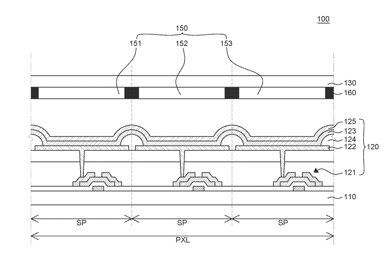
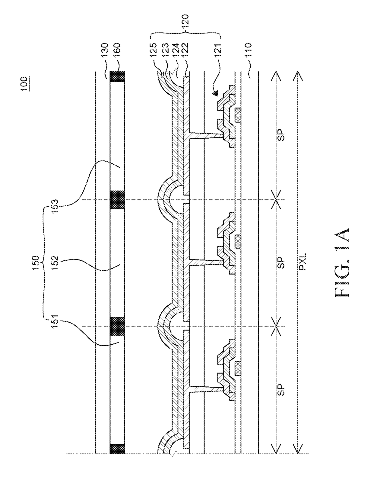
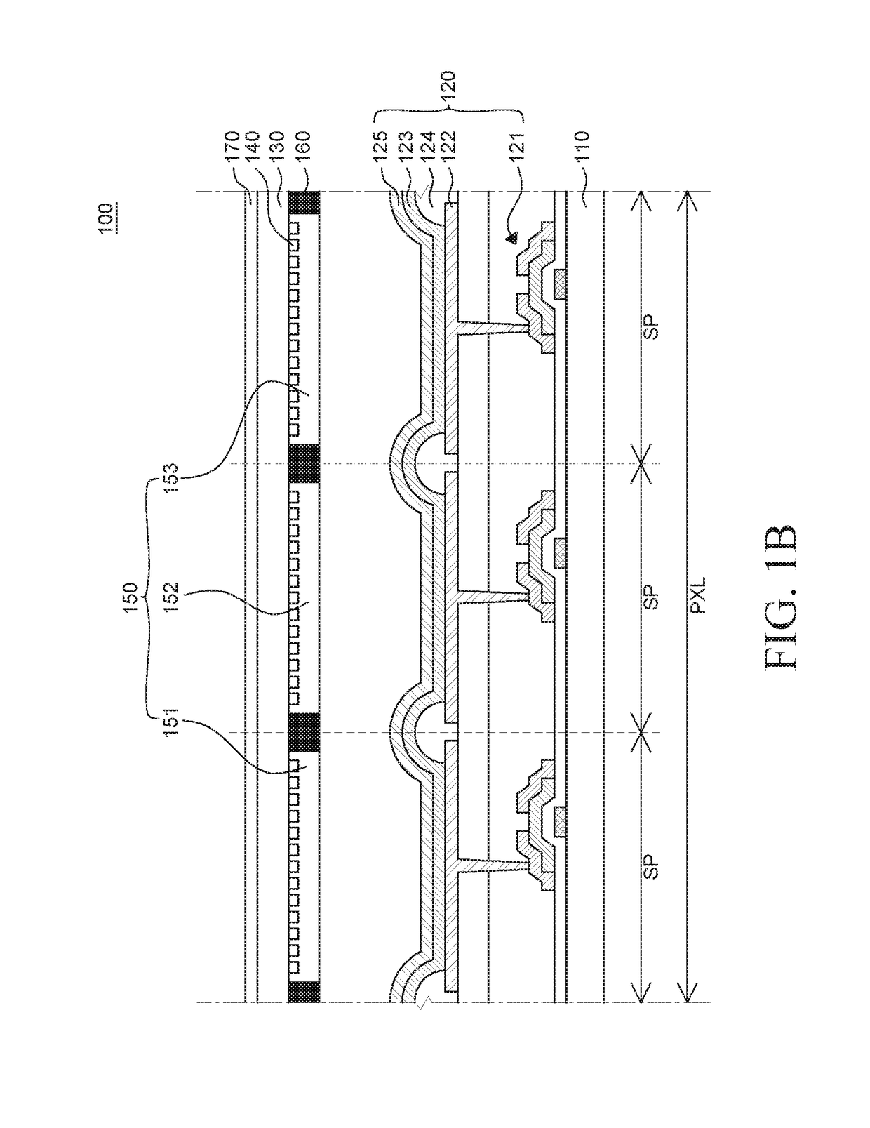
Disclosed herein is a display panel including a polarizing emission layer. An organic light emitting device is formed on a first substrate. A polarizing emission layer are formed on a second substrate facing the first substrate. The polarizing emission layer is formed in a subpixel area corresponding to the organic light emitting device. The polarizing emission layer includes quantum rods. The quantum rods are aligned in one direction to be polarized. Accordingly, loss of transmitting light in the display panel including the polarizing layer may be minimized. In addition, since colors are implemented by the quantum rods included in the polarizing emission layer, color filters can be replaced by the quantum rods, and loss of light resulting from the color filters may be minimized.

Description

CROSS-REFERENCED TO RELATED APPLICATIONS[0001]This application is the National Phase of PCT International Application No. PCT / KR2015 / 008597 filed on Aug. 18, 2015, which claims priority under 35 U.S.C. 119(a) to Korean Patent Application No. 10-2014-0113713 filed on Aug. 29, 2014 in Republic of Korea. All of these applications are hereby expressly incorporated by reference into the present application.BACKGROUND OF THE INVENTION[0002]Technical Field[0003]The present disclosure relates to a display panel and a method of manufacturing the same and, more particularly, a display panel provided with a polarizing emission layer to improve light efficiency and reduce power consumption and a method of manufacturing the same.[0004]Background Art[0005]Recently, display panels such as a liquid crystal display (LCD) and an organic light-emitting diode display (OLED) have come into the spotlight as flat display panels.[0006]In particular, the OLED, which is a self-luminous display device, does n...

Claims


Application Information

Patent Timeline
Patent Type & Authority Applications(United States)
IPC IPC(8): H01L51/52H01L51/56H01L27/32
CPCH01L51/5281H01L27/3244H01L2251/5369H01L51/5234H01L51/56H01L27/3211H10K59/35H10K59/38H10K2102/331H10K59/8791H10K59/8793H10K50/86H10K50/828H10K50/868H10K59/12H10K71/00
Inventor GEE, MOON BAEPARK, HAN SUNKIM, SU HYEON
Owner LG DISPLAY CO LTD
Learn More