
Retrofit light emitting diode tube

a technology of light-emitting diodes and retrofitting, which is applied in the field of light sources, can solve problems such as disadvantageous relays, and achieve the effect of low cos

Active Publication Date: 2017-09-07
SIGNIFY HLDG BV
View PDF6 Cites 1 Cited by
  • Summary
  • Abstract
  • Description
  • Claims
  • Application Information

AI Technical Summary

Benefits of technology

[0008]a converter circuit for converting the first signal into a second signal for feeding the light circuit, the converter circuit comprising a reactive circuit for matching the light circuit and the high-frequency ballast and for providing safety to a person when installing the light source.
[0028]A problem to provide an improved light source has been solved. A further advantage is that the improved light source is simple, robust and low cost.

Problems solved by technology

Such a relay is disadvantageous.

Method used


Image

  • Retrofit light emitting diode tube
  • Retrofit light emitting diode tube
  • Retrofit light emitting diode tube

Examples


first embodiment

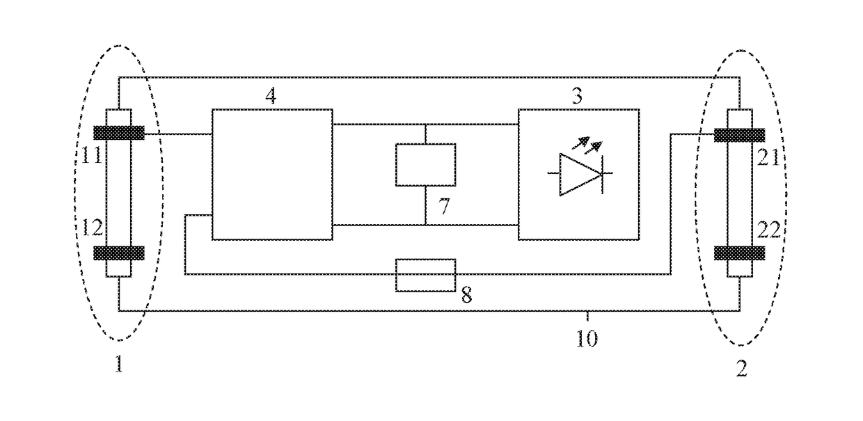
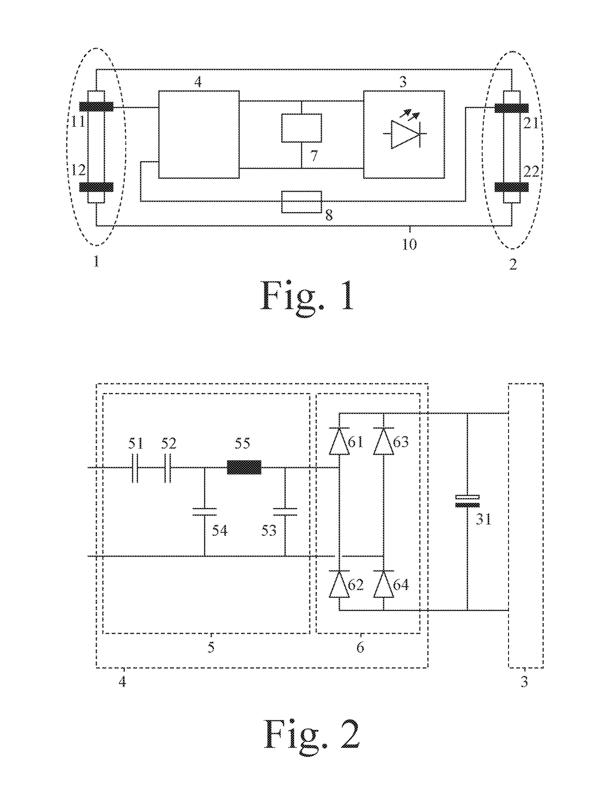
[0039]In the FIG. 1, a light source 10 is shown. The light source 10 comprises at a first end of a tube a first terminal 1 and at a second end of the tube a second terminal 2 for exchanging a first signal with a high-frequency ballast. The first terminal 1 comprises for example two first pins 11, 12 and the second terminal 2 comprises for example two second pins 21, 22. The light source 10 comprises a converter circuit 4 for converting the first signal into a second signal for feeding a light circuit 3 that comprises one or more light emitting diodes. The pin 11 is for example coupled to a first input of the converter circuit 4, and the pin 12 is not connected. The pin 21 is for example coupled to a second input of the converter circuit 4, and the pin 22 is not connected. First and second outputs of the converter circuit 4 are coupled to first and second electrodes of the light circuit 3. The converter circuit 4 comprises a reactive circuit for matching the light circuit 3 and the h...

second embodiment

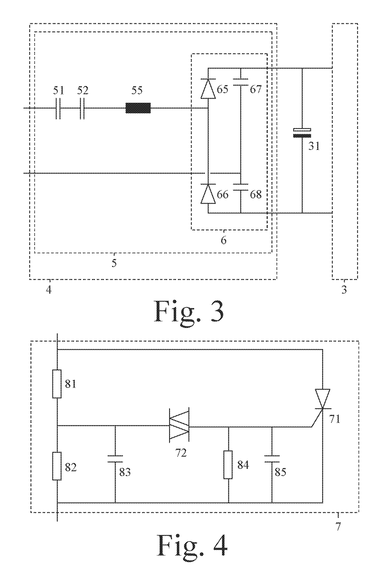
[0044]In the FIG. 3, a converter circuit 4 is shown. Here, the converter circuit 4 comprises a reactive circuit 5 for matching the light circuit 3 and the high-frequency ballast and for providing safety to a person when installing the light source 10. The matching comprises for example adjusting / defining amplitudes of the first and second signals. Said providing comprises for example adjusting / defining the amplitude of the first signal such that safety to a person who is installing the light source 10 is realized. This time, the reactive circuit 5 comprises a rectifier bridge 6 consisting of two diodes 65, 66 and two voltage-doubling capacitors 67, 68. Compared to the rectifier bridge 6 consisting of four diodes 61-64, the rectifier bridge 6 consisting of two diodes 65, 66 and two voltage-doubling capacitors 67, 68 will increase an output voltage of the converter circuit 4 and reduce an output current of the converter circuit 4.

[0045]This reactive circuit 5 further comprises one pro...


PUM


Abstract

Light sources for replacing fluorescent lamps comprise light circuits with light emitting diodes, first and second terminals located at first and second ends of the light sources for exchanging first signals with high-frequency ballasts, and converter circuits for converting the first signals into second signals for feeding the light circuits. The converter circuits comprise reactive circuits for matching the light circuits and the high-frequency ballasts and provide safety to persons when installing the light sources. The light sources may further comprise protection circuits for protecting parts of the light sources against problems. The protection circuits may comprise monitor circuits for monitoring parameters of the light sources and for in response to monitoring results short-circuiting outputs of the converter circuits, and fuses. The reactive circuits may comprise protecting capacitors.

Description

CROSS REFERENCE TO RELATED CASES[0001]This application is a Divisional application of pending U.S. Ser. No. 14 / 895,555, filed on Dec. 3, 2015, which is the U.S. National Phase Application of International Application No. PCT / EP2014 / 062538, filed Jun. 16, 2014 and claims the benefit of European Patent Aplication 13173977.3, filed Jun. 27, 2013. These applications are hereby incorporated by reference.FIELD OF THE INVENTION[0002]The invention relates to a light source comprising a light circuit with one or more light emitting diodes. Examples of such a light source are retrofit light emitting diode tubes.BACKGROUND OF THE INVENTION[0003]US 2012 / 0181952 A1 discloses a drive circuit for a light emitting diode array. To enable a safe mounting, the drive circuit comprises a safety circuit for controlling a relay. Such a relay is disadvantageous.SUMMARY OF THE INVENTION[0004]It is an object of the invention to provide an improved light source comprising a light circuit with one or more ligh...

Claims


Application Information

Patent Timeline
Patent Type & Authority Applications(United States)
IPC IPC(8): H05B33/08H05B44/00H05B45/50H05B45/59
CPCY02B20/383H05B33/0884Y02B20/341Y02B20/386H05B33/0809H05B45/50Y02B20/30H05B45/395H05B47/24H05B47/25H05B45/59
Inventor TAO, HAIMIN
Owner SIGNIFY HLDG BV
Learn More