Field cultivator sweep

a cultivator and field technology, applied in the field of cultivator sweep, can solve the problems of difficult for the roots of the crop to grow into or below the compressed soil, and achieve the effect of enhancing plant root growth and minimizing soil compaction

Inactive Publication Date: 2017-09-14
HEMERSON AL
View PDF4 Cites 3 Cited by
  • Summary
  • Abstract
  • Description
  • Claims
  • Application Information

AI Technical Summary

Benefits of technology

[0015]The field cultivator sweep of the present invention includes opposite left and right wings which extend outwardly and rearedly from a center line so as to form a symmetrical body with a V-shaped leading edge. An upstanding neck is provided on the body for mounting to sweep to a shank of a cultivator. A soil conditioning element extends downwardly from the bottom of the body. In a preferred embodiment, the conditioning element is a flat blade with a rearwardly angled leading edge. The blade creates a vertical slit in the soil as the sweep is pulled through the ground, thereby minimizing soil compaction and enhancing plant root growth.

Problems solved by technology

However, the sweeps have a tendency to compress the soil beneath the sweep, which makes it difficult for the roots of the crop to grow into or below the compressed soil.

Method used


Image

  • Field cultivator sweep
  • Field cultivator sweep
  • Field cultivator sweep

Examples


Embodiment Construction

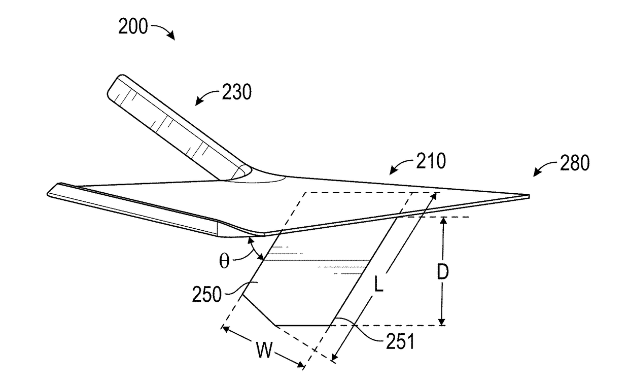
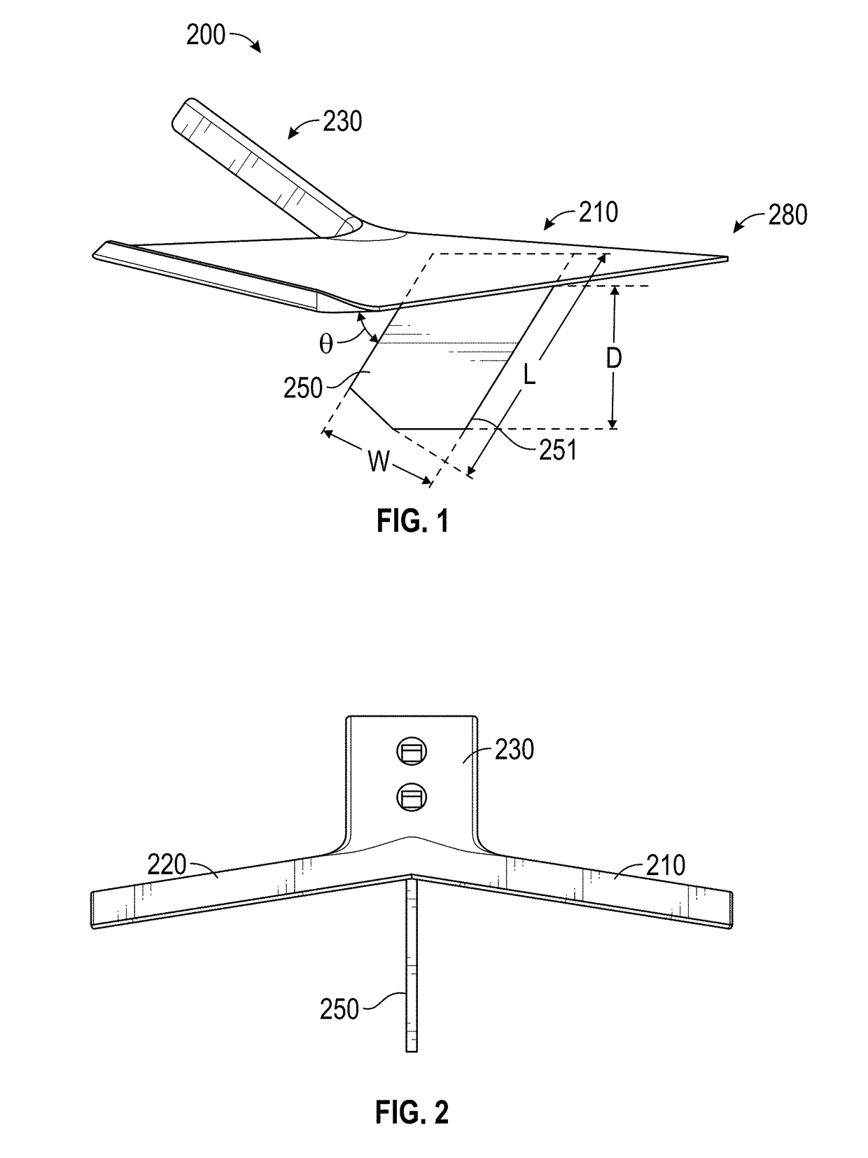
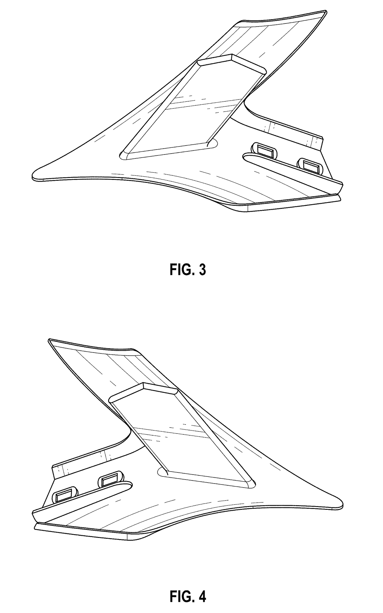
[0032]FIGS. 1-4 show a preferred embodiment of a field cultivator sweep 200 in accordance with the present invention. The field cultivator sweep 200 includes a first wing 210 and second wing 220, together forming a wing body, and an upstanding neck 230 at the rear of the body. The neck 230 is configured to attach to a shank of a cultivator. To this end, the neck 230 may include a plurality of apertures to connect the cultivator sweep 200 to the shank. For example, in FIG. 2 the field cultivator sweep 200 is illustrated as having two apertures 232 and 234 to allow the field cultivator sweep 200 to connect to the shank by a pair of bolts. It is understood the above connecting method is merely exemplary as the field cultivator sweep 200 may be attached to the shank by a different method, for example, by clamps, pins, screws, and welding. Furthermore, the number of apertures illustrated in FIG. 2 is not meant to be a limiting feature since some embodiments of the cultivator sweep 200 ma...


PUM


Abstract

The field cultivating sweep includes a body with wings extending from a center line in opposite directions, and a conditioning element extending downwardly from the wing body. The conditioning element may be a blade extending vertically downwardly along the center line of the body and having a leading edge sloped rearedly from front to back. In alternative embodiments, the conditioning element may have a triangular or rectangular shape or may be in the form of a fluted coulter. The conditioning element acts to till the ground vertically and break up compacted soil as the sweep is drawn along the ground.

Description

CROSS-REFERENCE TO RELATED APPLICATIONS[0001]This is a Continuation Application of U.S. Ser. No. 15,452,120, filed Mar. 7, 2017, which claims priority to previously filed provisional applications U.S. Ser. No. 62 / 385,727, filed on Sep. 9, 2016; U.S. Ser. No. 62 / 384,579, filed Sep. 7, 2016; U.S. Ser. No. 62 / 383,945, filed on Sep. 6, 2016; U.S. Ser. No. 62 / 339,592, filed May 20, 2016; and U.S. Ser. No. 62 / 305,339, filed on Mar. 8, 2016; all of which are herein incorporated by reference in their entirety.FIELD OF THE INVENTION[0002]The present invention relates to a tool for improved soil tillage, and particularly to an agricultural field cultivator sweep having a soil conditioner for improved vertical tillage.BACKGROUND OF THE INVENTION[0003]Field cultivator sweeps are well known in the agricultural industry. These sweeps are pulled through the ground to loosen the soil for seeding. These sweeps are also used to remove weeds which otherwise absorb nutrients and moisture from the soil....

Claims


Application Information

Patent Timeline
Patent Type & Authority Applications(United States)
IPC IPC(8): A01B35/26
CPCA01B35/26A01B13/08A01B23/02A01B37/00
Inventor HEMERSON, AL
Owner HEMERSON AL
Why Eureka
Try Eureka