Liquid fertilizer injection method, system, and apparatus

Inactive Publication Date: 2007-12-20
CHEN YING +1
View PDF5 Cites 15 Cited by
  • Summary
  • Abstract
  • Description
  • Claims
  • Application Information

AI Technical Summary

Benefits of technology

[0016] In a second aspect of the invention, there is provided a soil-cutting apparatus for creating a sub-surface cavity while minimizing compaction of soil surrounding the cavity, wherein the cutting apparatus includes at least one cutting blade for slicing into the soil surface to create an opening at the soil surface and a cavity below the level of the soil surface.
[0020] In a third aspect, there is provided a dispensing system for delivering liquid fertilizer to at least one soil sub-surface cavity having an opening at the soil surface, the system including at least one metering valve assembly for controlling the dispensing of fertilizer through any suitable injection device such that the fluid volume of liquid fertilizer dispensed corresponds to the fluid capacity of the cavity so as to avoid or minimize overflow onto the soil surface surrounding each opening.
[0026] In a fourth aspect of the invention, there is provided an apparatus for applying liquid fertilizer to a region of crop or forage ground having a soil surface, the apparatus including a mobile platform for travelling over a region of crop or forage ground; a soil-cutting apparatus operably attached to the mobile platform, the soil-cutting apparatus including at least one cutting blade for slicing into the soil surface to create an opening at the soil surface and a cavity under the soil surface, while minimizing compaction of soil surrounding the cavity; a liquid fertilizer dispenser associated with the soil-cutting apparatus, the dispenser including at least one metering valve assembly for controlling the dispensation of fertilizer through at least one associated injection device; and a synchronization system for associating the metered fluid volume of liquid fertilizer dispensed with the location and size of each cavity; wherein as the mobile platform travels over the soil surface of the ground, cavities are created by the soil-cutting apparatus, and liquid fertilizer is delivered directly to each cavity by the dispensing system as determined by the synchronization system, in an amount less than or equal to the fluid capacity of each cavity so as to minimize overflow onto the soil surface surrounding each opening.

Problems solved by technology

However, all stakeholders recognise that some adverse environmental impacts are associated with manure application, such as nutrient loss through volatilization, nuisance odour emissions, and runoff of phosphorus to surface water.
In grassland (e.g. hay or other forage) applications, the “painting” of existing crops with liquid manure provides additional area having exposed manure, which aggravates the problem of volatilization loss and odour, in addition to contaminating the forage leading to potentially pathogenic activities not desirable for animal grazing.
Using a dribble bar, manure is delivered near and above the surface of the ground by pouring it out at low pressure leaving less than 100% of the surface covered with bands of manure, but still suffering from substantial evaporation, volatilization, odour, and contamination of feed or crops.
Surface incorporation usually is not an option for cropland where the tillage action would damage the crop stands.
Disadvantageously, plant damage reducing yield, limits the applicability of such operations.
Further, the high power requirement associated with soil cutting consumes large amounts of fuel, which adversely affects the economics of the farming operation that it supports.
Disadvantageously, although part of the manure eventually runs into the perforations, the delivery of the fertilizing fluids above the surface still results in significant volatilization loss, odour, and contamination, such that this method is not classified as “injection” by regulatory bodies.
Disadvantageously, the indiscriminate delivery of manure slurry continuously along the line formed by the depressions results in significant contamination since the manure is not just deposited within the openings, but rather spills over onto both the forage and the surface of the ground between adjacent depressions.
Disadvantageously, the system of Hatlo relies on significant and stable pump pressure in order to bore down to a consistent penetration depth, which choice of a complex sub-assembly leads to the need for substantial maintenance of the system.
Further, the shoe element dragged along the ground tends to disturb forage by flattening anything along each of a series of continuous paths.

Method used


Image

  • Liquid fertilizer injection method, system, and apparatus
  • Liquid fertilizer injection method, system, and apparatus
  • Liquid fertilizer injection method, system, and apparatus

Examples


Embodiment Construction

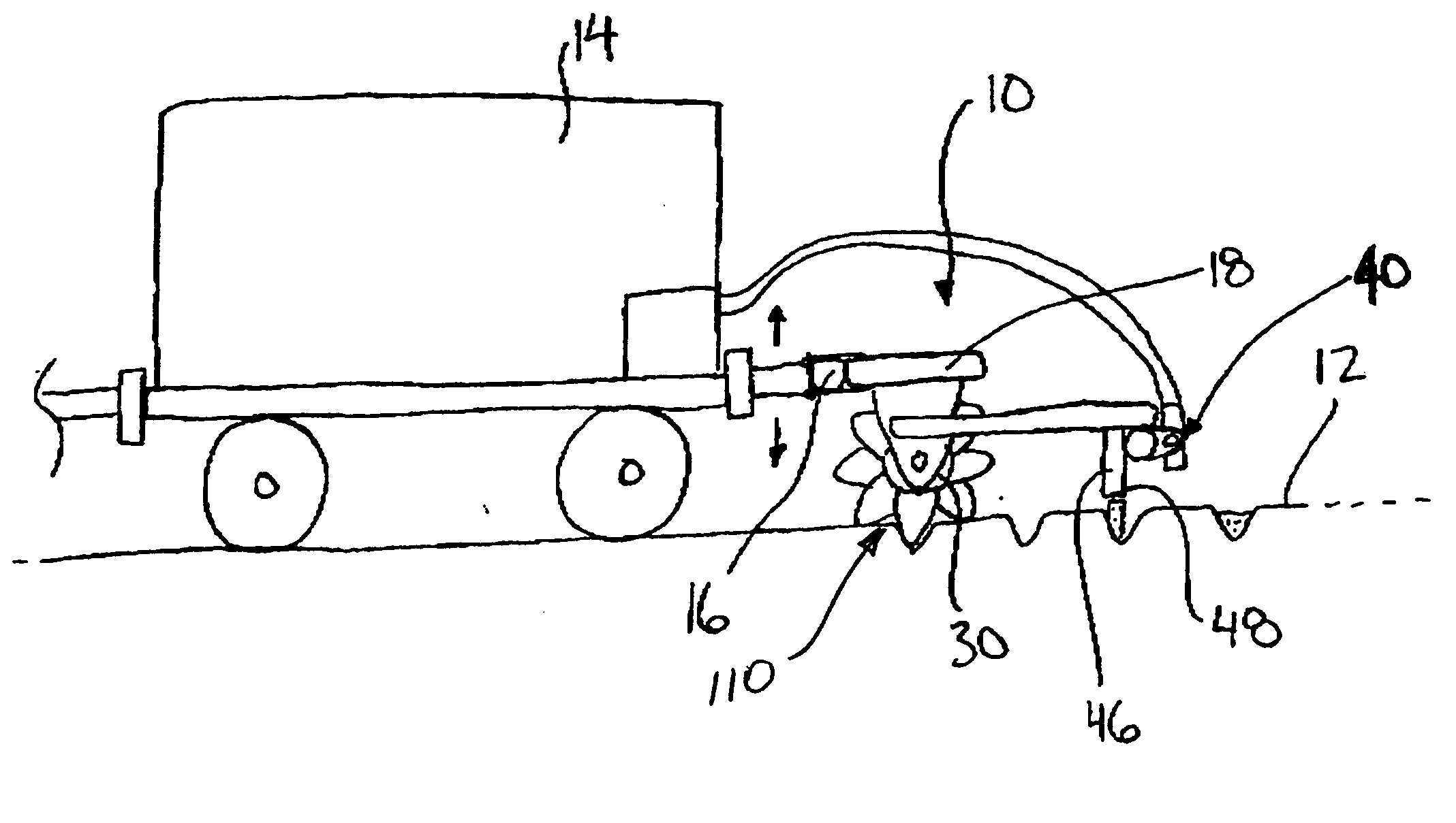
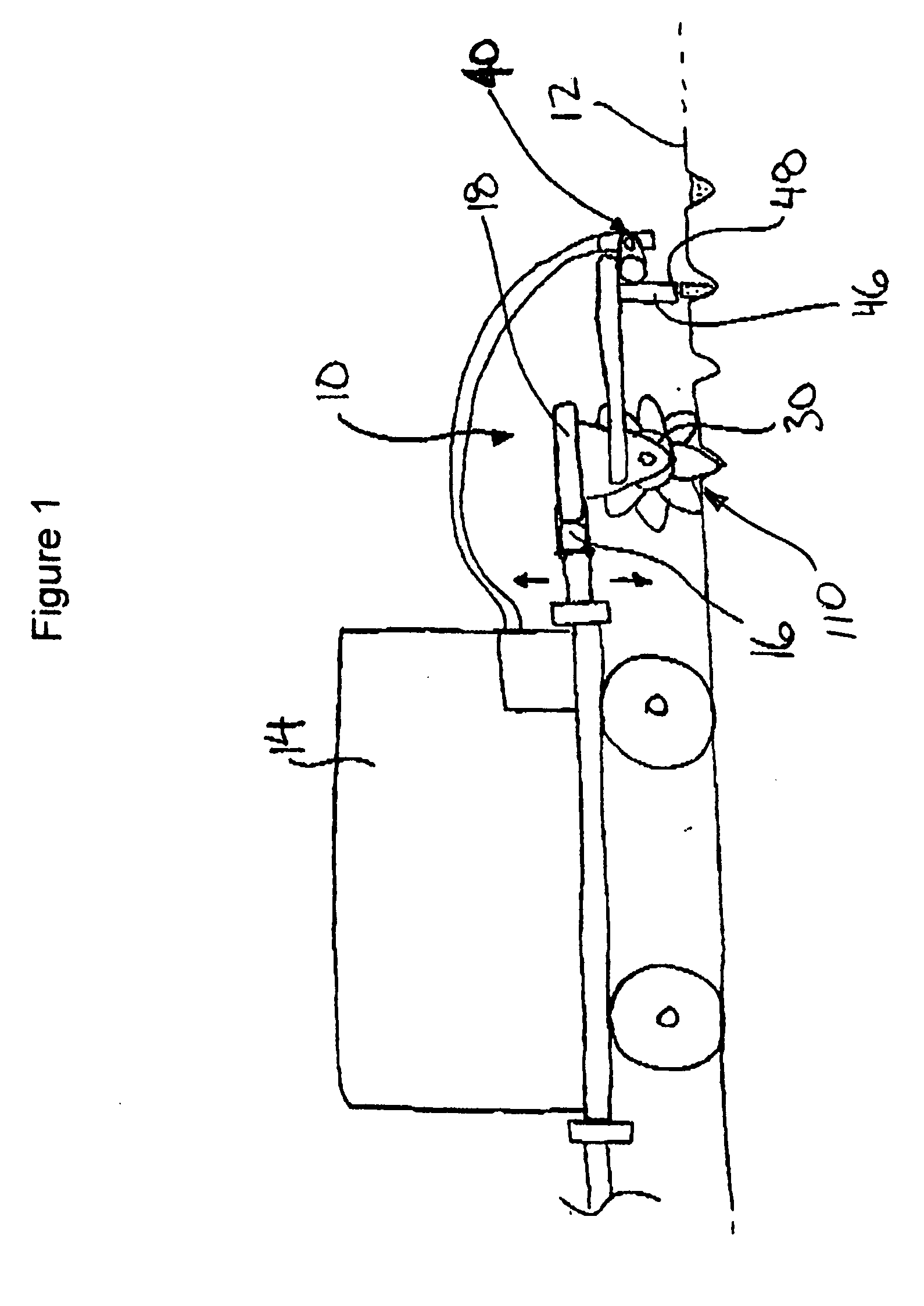
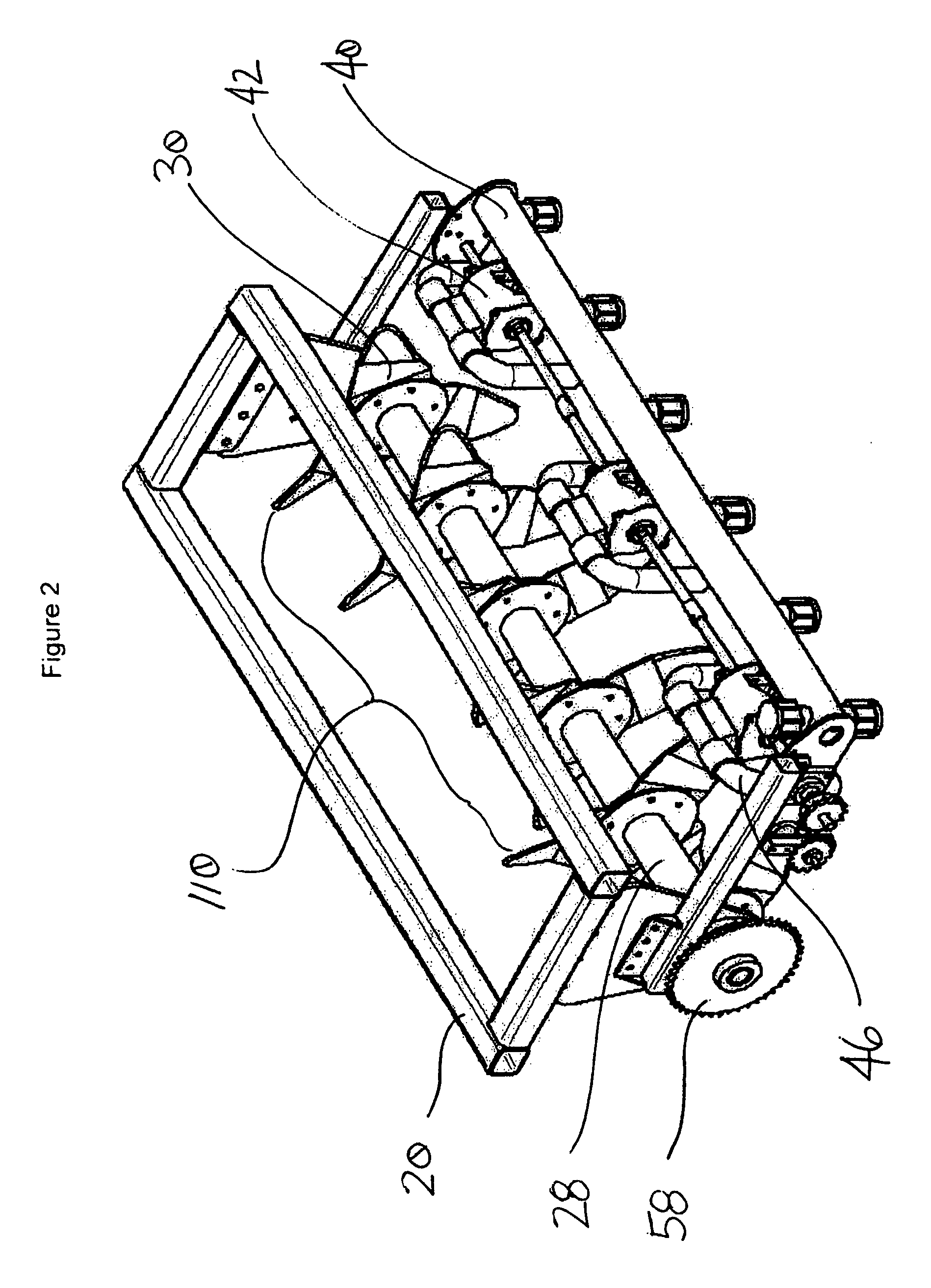
[0037] Referring to FIGS. 1 through 8 there is depicted one embodiment, denoted generally as 10, of the system of the invention for the controlled flow injection of liquid fertilizer into ground 12 (any appropriate crop or forage land). A source 14 (e.g. a tank) of liquid fertilizer supplies manifold 40 through at least one flow metering valve 42 (details seen in FIG. 6), sometimes referred to as a “pulsing valve assembly”, for periodically dispensing a definable volume of liquid. System 10 is typically located behind a source 14 (on any suitable moving platform) and supported for rolling movement along ground 12 behind a towing vehicle (not shown). Draw bar 16 as shown provides for height adjustment of system 10 in relation to ground 12. System 10 uses frame 18 to support soil cutting assembly 110 (wheels 30 on shaft 28 as defined in more detail below) that when towed across ground 12 cuts a plurality of low-compaction, spaced openings that may subsequently be filled with metered a...


PUM


Abstract

A method is described for cutting sub-surface cavities into a region of soil and for delivering liquid fertilizer directly to each cavity while minimizing overflow or spillage of liquid fertilizer onto the surrounding surface soil. A cutting apparatus is described for creating sub-surface cavities the soil, each cavity is associated with an opening at the soil surface through which liquid fertilizer can be delivered to the cavity. A system for delivery of liquid fertilizer to the cavities is described, which includes a fertilizer dispenser including a metering valve assembly for delivery of liquid fertilizer to each cavity. A synchronization system may be incorporated into the system for locating each cavity and directing the dispensing of liquid fertilizer.

Description

RELATED APPLICATIONS [0001] This application claims the benefit of U.S. Provisional Application No. 60 / 561,916 filed 14 Apr. 2004.FIELD OF THE INVENTION [0002] The present invention relates generally to injecting liquid fertilizer, such as liquid manure, into the ground, and specifically to a method and metering equipment for doing so while causing: low disturbance to the surface, low contamination of and damage to vegetation, and high absorption by the soil. BACKGROUND [0003] Land application of liquid manure has been recognised as a cost-effective and sustainable practice for using manure. Comparable crop yields can be achieved when using liquid manure to replace chemical fertilisers. However, all stakeholders recognise that some adverse environmental impacts are associated with manure application, such as nutrient loss through volatilization, nuisance odour emissions, and runoff of phosphorus to surface water. Known techniques for manure application include: 1) Broadcasting [000...

Claims


Application Information

Patent Timeline
IPC IPC(8): A01G25/09A01B5/00A01B13/08A01B33/16A01B49/06A01B79/02A01C23/02
CPCA01B33/16A01C23/026A01B49/065
Inventor CHEN, YINGLEAFLOOR, ERRON JAMES
Owner CHEN YING
Why Eureka
Try Eureka