Electrical connector limiter structure of wire connection terminal

a limiter and wire connection technology, applied in the direction of connection, clamp/spring connection, electrical equipment, etc., can solve the problems of metal bare end of conductive wire thrusting and damaging the case, troublesome and time-consuming processing of the limiter, and preventing the deflecting of metal leaf springs in the operation, so as to facilitate operation and facilitate the operation. , the effect of enhancing the stability of operation and motion

Active Publication Date: 2017-09-14
SWITCHLAB +1
View PDF18 Cites 3 Cited by
  • Summary
  • Abstract
  • Description
  • Claims
  • Application Information

AI Technical Summary

Benefits of technology

[0011]It is therefore a primary object of the present invention to provide an electrical connector limiter structure of wire connection terminal is easily operable to enhance the stability of the operation and motion of metal leaf springs. The wire connection terminal includes conductive components mounted in the insulation case and electrical connector assembled with the conductive components. The electrical connector has a limiter for receiving the metal

Problems solved by technology

It often takes place that when the conductive wire is plugged into the case, due to the large number of plug-in operation and human negligence, the metal bare end of the conductive wire thrusts and damages the case or deflects the metal leaf spring to scrape and break the case and fail to stably hold the conductive wire.
However, as well known by those who are skilled in this field, such limiter assembled with the wire connector or the conductive plate has a relatively complicated structure and it is troublesome and time-consuming to process the limiter.
This will lead to increase of the total volume of the wiring device and occupy extra space.
Also, this is unbeneficial to the development and design trend of miniaturized wire connection terminal.
For example, in the condition that the develo

Method used


Image

  • Electrical connector limiter structure of wire connection terminal
  • Electrical connector limiter structure of wire connection terminal
  • Electrical connector limiter structure of wire connection terminal

Examples


Embodiment Construction

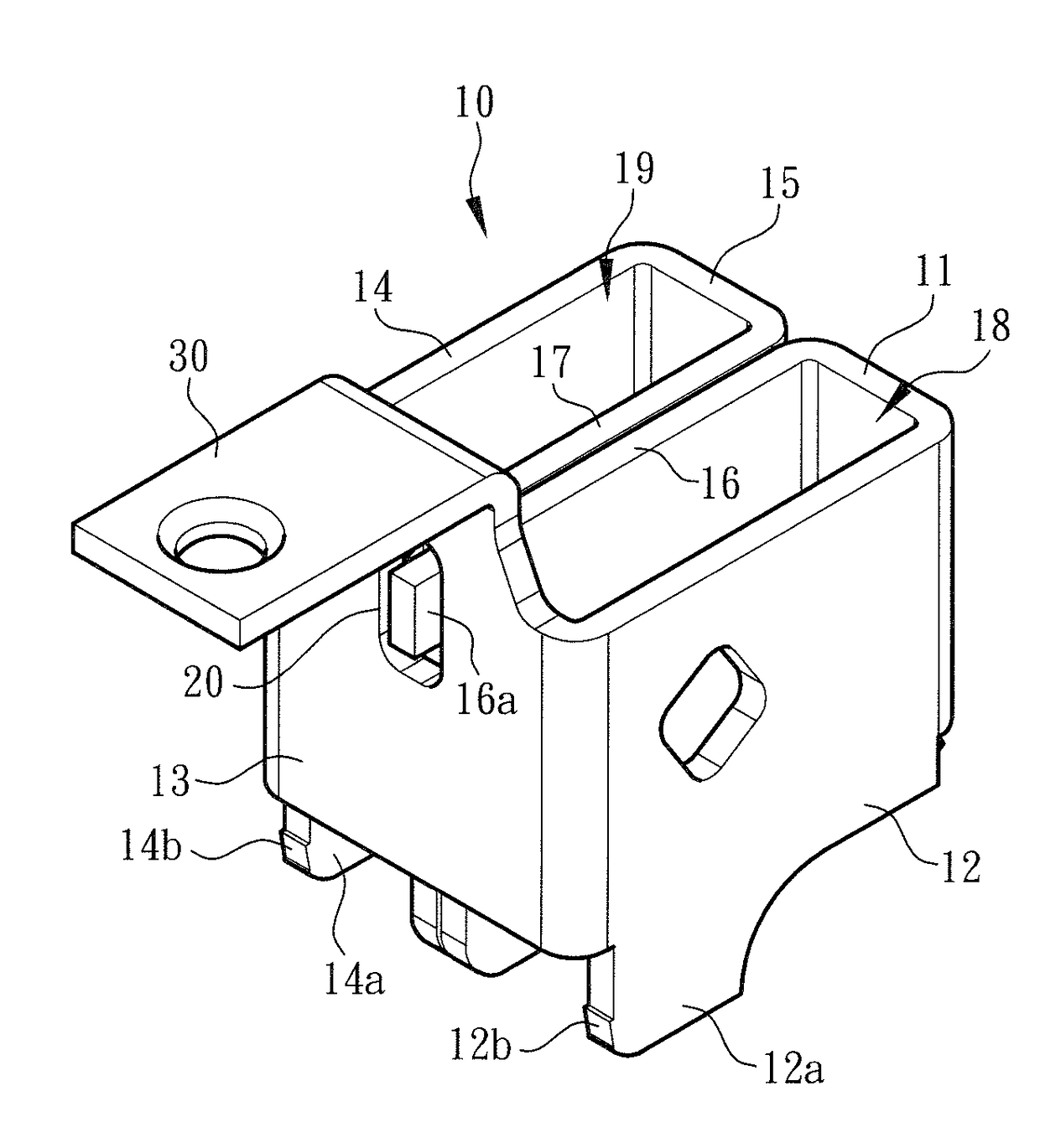
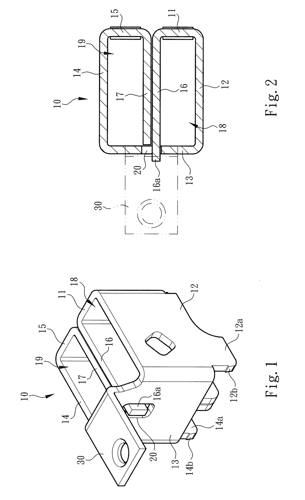
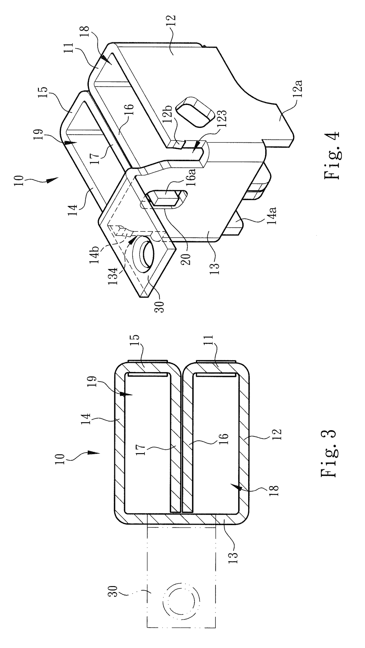
[0032]Please refer to FIGS. 1, 2 and 3. The electrical connector limiter structure of wire connection terminal of the present invention is mountable in an insulation case and assembled with a conductive support, an electrical connector and metal leaf spring to form a pushbutton switch device, electrical connection terminal or the like device for pivotally connecting with a wiring circuit or conductive wire coming from an electronic or electrical apparatus. (This pertains to prior art and thus is not shown in the drawings). Basically, according to the application form or mode, the limiter 10 permits at least two conductive wires to plug in and assemble with the metal leaf springs.

[0033]In a preferred embodiment, the limiter 10 is selectively made of a flat blank material with higher rigidity or hardness, such as iron, steel, etc. The flat blank material is processed to form a rectangular frame structure of the limiter 10 as shown in FIGS. 1, 2 and 3.

[0034]As shown in the drawings, th...


PUM


Abstract

An electrical connector limiter structure of wire connection terminal is easily operable to enhance the stability of the operation and motion of metal leaf springs. The wire connection terminal includes conductive components mounted in the insulation case and electrical connector assembled with the conductive components. The electrical connector has a limiter for receiving the metal leaf springs and restricting moving path thereof. The limiter is partitioned to define a first space and a second space with fully closed peripheries, in which the metal leaf springs are mounted. The wiring circuits or conductive wires coming from an apparatus can be easily directly plugged into the first and second spaces of the limiter to insert with the metal leaf springs. The limiter serves to prevent the metal leaf springs from deflecting in operation.

Description

BACKGROUND OF THE INVENTION[0001]1. Field of the Invention[0002]The present invention relates generally to an electrical connector limiter structure of wire connection terminal, and more particularly to an electrical connector limiter assembled with metal leaf springs. The limiter has higher rigidity and is able to help in fixing and restricting moving path of the metal leaf springs.[0003]2. Description of the Related Art[0004]A conventional wire connection terminal device has an insulation case (generally made of plastic material), a metal component (or so-called electrical conductive component) and a metal leaf spring. The metal component and the metal leaf spring are enclosed in the insulation case to press and electrically connect with a conductive wire plugged in the terminal device. The terminal device can be mounted on an operation panel or a distributor box of an electronic or electrical apparatus as an electrical wiring connection device.[0005]With respect to the operation ...

Claims


Application Information

Patent Timeline
IPC IPC(8): H01R4/48
CPCH01R4/4809
Inventor WU, CHIH-YUANWU, CHERNG SHIN
Owner SWITCHLAB
Why Eureka
Try Eureka