Headlamp aiming tool and method

a technology of aiming tool and headlamp, which is applied in the direction of mechanical measuring arrangement, optical apparatus testing, instruments, etc., can solve the problems of cumbersome operation and unsuitable aiming halogen type, and achieve the effect of maximizing roadway lighting, minimizing glare, and increasing the installed height of the headlamp assembly

Active Publication Date: 2017-09-21
AMERICAN AUTOMOBILE ASSOCIATION
View PDF11 Cites 2 Cited by
  • Summary
  • Abstract
  • Description
  • Claims
  • Application Information

AI Technical Summary

Benefits of technology

[0008]The vehicle headlamp center position is determined by measuring the height of a center portion of each headlamp relative to a support surface for the vehicle, measuring the distance between the center portions of the headlamps, and translating the height and distance measurements to the screen relative to the vehicle centerline on the screen. In addition, the distance between the light source, i.e. the bulb for each of the headlamps and the screen is measured. A beam offset for each headlamp is calculated as a function of the height of the headlamps and the distance between the headlamps and the screen. Vertical offset is calculated to maximize roadway lighting while minimizing glare. This approach is also suitable for modified vehicles such as trucks and sport utility vehicles that have been altered such as by lifting, thereby increasing the installed height of the headlamp assemblies. The horizontal offset is available to implement based on local ordinance or vehicle manufacturer recommendations. The headlamps are adjusted so that the area of highest intensity for each headlamp is aligned in accordance with the beam offset.

Problems solved by technology

While the prior devices operate satisfactorily, they are not suitable for aiming halogen type headlights and are cumbersome for the technician to operate.

Method used


Image

  • Headlamp aiming tool and method
  • Headlamp aiming tool and method
  • Headlamp aiming tool and method

Examples


Embodiment Construction

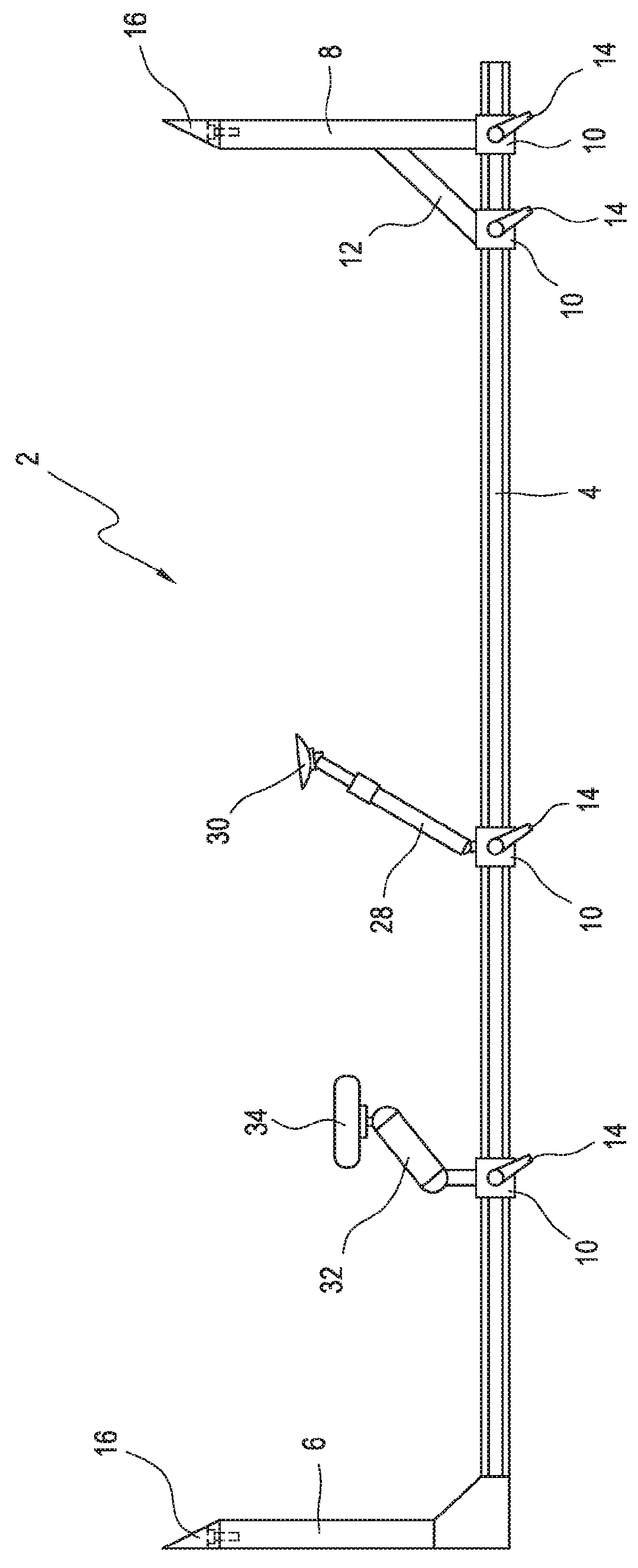
[0021]Referring first to FIG. 1, the headlamp aiming tool 2 according to the invention will be described. The tool is preferably formed of a strong, lightweight material such as aluminum. It includes a linear member 4 and a plurality of legs connected with the member. The first leg 6 is secured to one end of the linear member 4 and is not movable. It is arranged generally perpendicular to the linear member. A second leg 8 is arranged on the linear member spaced from the first leg. The second leg is also generally perpendicular to the linear member, extending in the same direction as the first leg 6. The second leg is movable along the linear member, such as by sliding, and includes at least one locking device 10 to lock the second leg in a selected position as will be developed below. A brace 12 may be connected with the second leg and is also slidably connected with the linear member via a locking device to maintain the second leg in a perpendicular relation relative to the linear ...


PUM


Abstract

A headlamp aiming tool includes a linear member and four legs, the first of which is connected with one end of the member and the second, third and fourth of which are adjustable relative to the linear member. The first and second legs of the tool are used to measure the distance between the headlamps of a vehicle and the height of the headlamps relative to the ground or floor. The tool may also be mounted on the vehicle via the first and second legs and a fastener connected with the third leg arranged between first and second legs. Lastly, the tool includes a laser device connected with the fourth leg which is also between the first and second legs. The laser device can be aligned with a centerline of the vehicle to direct a laser beam against a screen in front of the vehicle to indicate the vehicle centerline on the screen. The headlamp light and spacing measurements are used to provide headlamp center points on the screen and to determine the horizontal and vertical offset of the low beam light from each headlamp. The offset is used to adjust the headlamps so that they are properly aimed.

Description

BACKGROUND OF THE INVENTION[0001]Vehicle headlamps operate most efficiently when they are aimed properly. Similarly, properly aimed headlamps are not a distraction or nuisance to oncoming motorists. The headlamps are normally set for proper aim or alignment when the vehicle is manufactured. However, through use, accident, or replacement, the headlamps often become misaligned.[0002]With the recent conversion of most headlamps to halogen bulbs, alignment becomes more difficult because the beam or light dispersion differs from that of prior incandescent bulbs which produced a more focused pattern which was easier to align. Most automobile repair shops do not have the appropriate tools or equipment necessary to re-aim a headlamp for optimum performance and efficiency. Moreover, many states no longer require headlamp aiming checks during inspection of motor vehicles. Thus, headlamp aiming has become a random hit or miss proposition with technicians being limited to guesstimating if a hea...

Claims


Application Information

Patent Timeline
Patent Type & Authority Applications(United States)
IPC IPC(8): G01B5/00B60Q1/04G01B11/27G01B5/14G01B3/04G01B3/20B60Q1/00G01B5/06
CPCG01B5/0025B60Q1/0064B60Q1/04G01B5/065B60Q2200/30G01B3/04G01B3/20G01B11/27G01B5/14G01M11/061G01M11/062G01M11/06
Inventor SHUMATE, DWAYNE
Owner AMERICAN AUTOMOBILE ASSOCIATION
Why Eureka
Try Eureka