Encoding device and method, decoding device and method, and program

a decoding device and a technology for encoding devices, applied in the field of encoding, can solve the problems of increasing the fundamental delay between the signal encoding and the decoding, increasing the amount of throughput and memory usage, and difficult to install a decoding device in a resource-poor setting such as an embedded device, and achieve the effect of high-quality sound

Active Publication Date: 2017-09-21
SONY CORP
View PDF3 Cites 1 Cited by
  • Summary
  • Abstract
  • Description
  • Claims
  • Application Information

AI Technical Summary

Benefits of technology

[0037]According to the first aspect and the second aspect of the present technology, high-quality sound can be obtained even in a resource-poor setting.
[0038]It should be noted that the effects of the present technology are not limited to the effects described herein, and may include any of the effects described in the present disclosure.

Problems solved by technology

Where a band dividing filter and a band combining filter are used as above, however, the fundamental delay between the signal encoding and the decoding is increased due to the filtering processes such as the band dividing process and the band combining process.
As a result, the amount of throughput and the memory usage greatly increase, which makes it difficult to install a decoding device in a resource-poor setting, such as an embedded device.

Method used


Image

  • Encoding device and method, decoding device and method, and program
  • Encoding device and method, decoding device and method, and program
  • Encoding device and method, decoding device and method, and program

Examples


first embodiment

[0058]

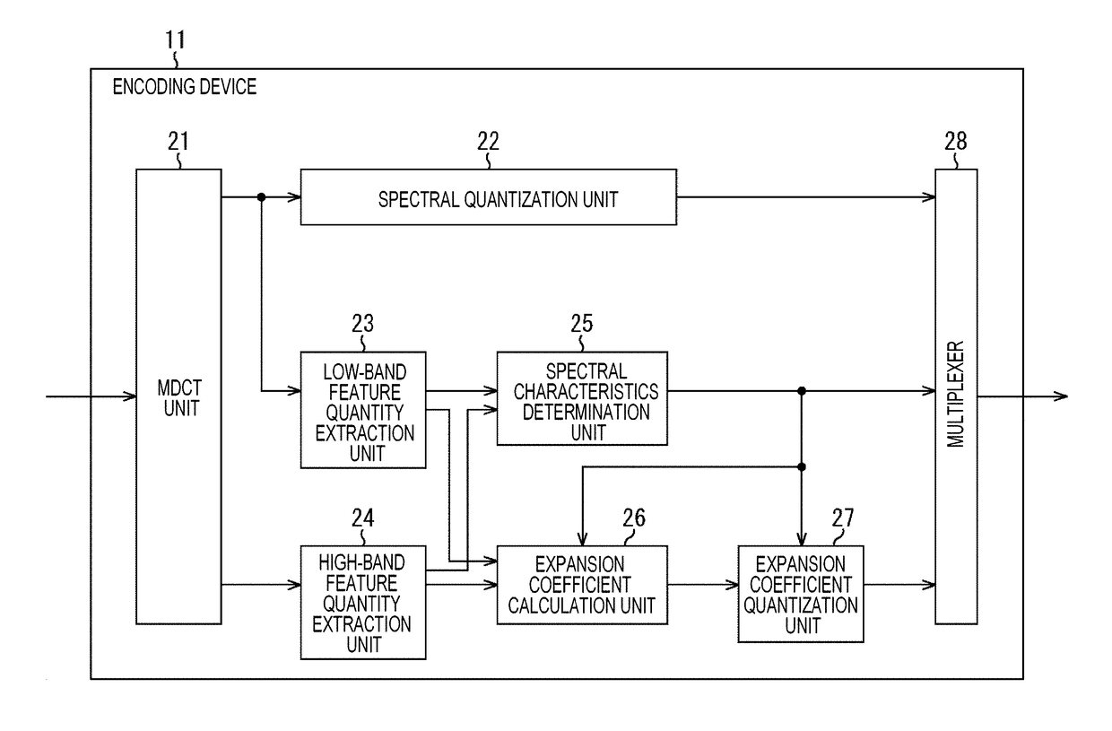
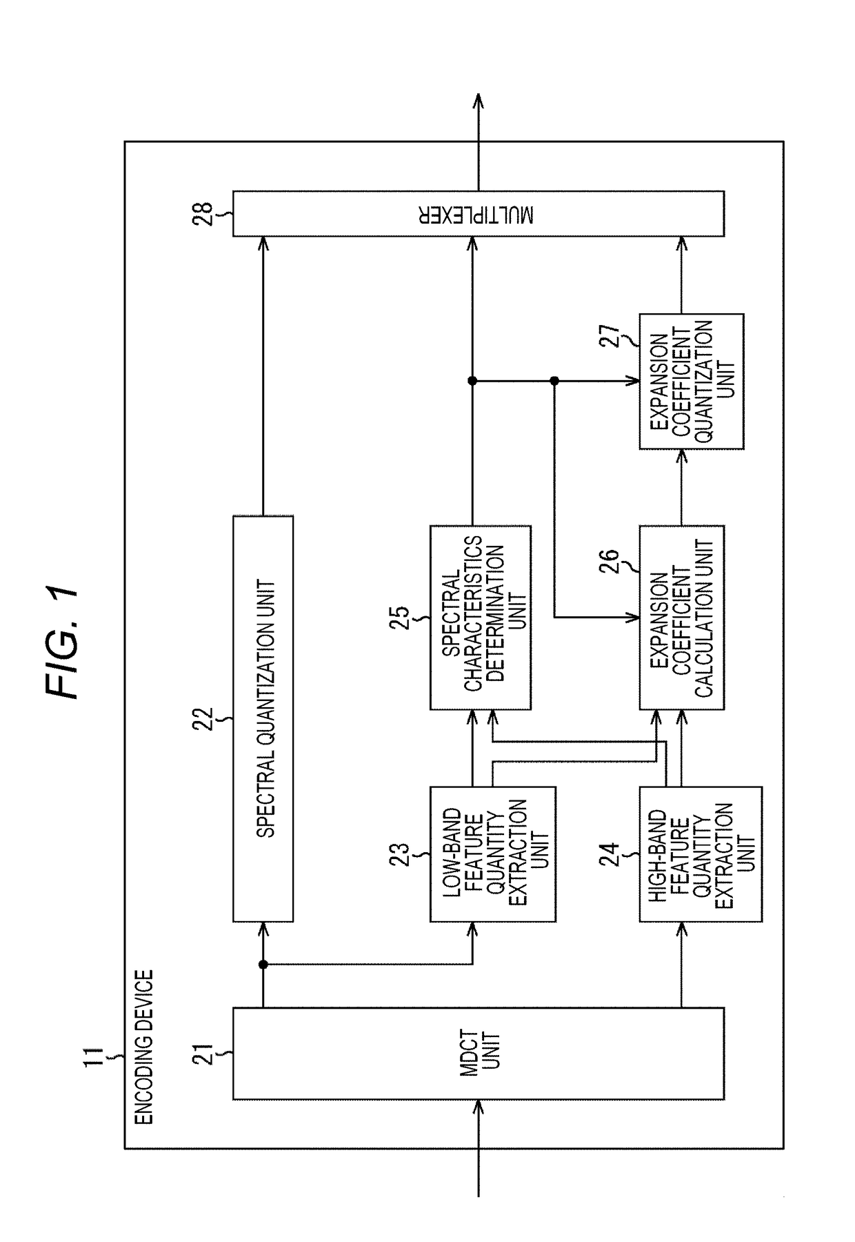
[0059]FIG. 1 is a diagram showing an example configuration of an embodiment of an encoding device to which the present technology is applied.

[0060]The encoding device 11 shown in FIG. 1 includes an MDCT unit 21, a spectral quantization unit 22, a low-band feature quantity extraction unit 23, a high-band feature quantity extraction unit 24, a spectral characteristics determination unit 25, an expansion coefficient calculation unit 26, an expansion coefficient quantization unit 27, and a multiplexer 28.

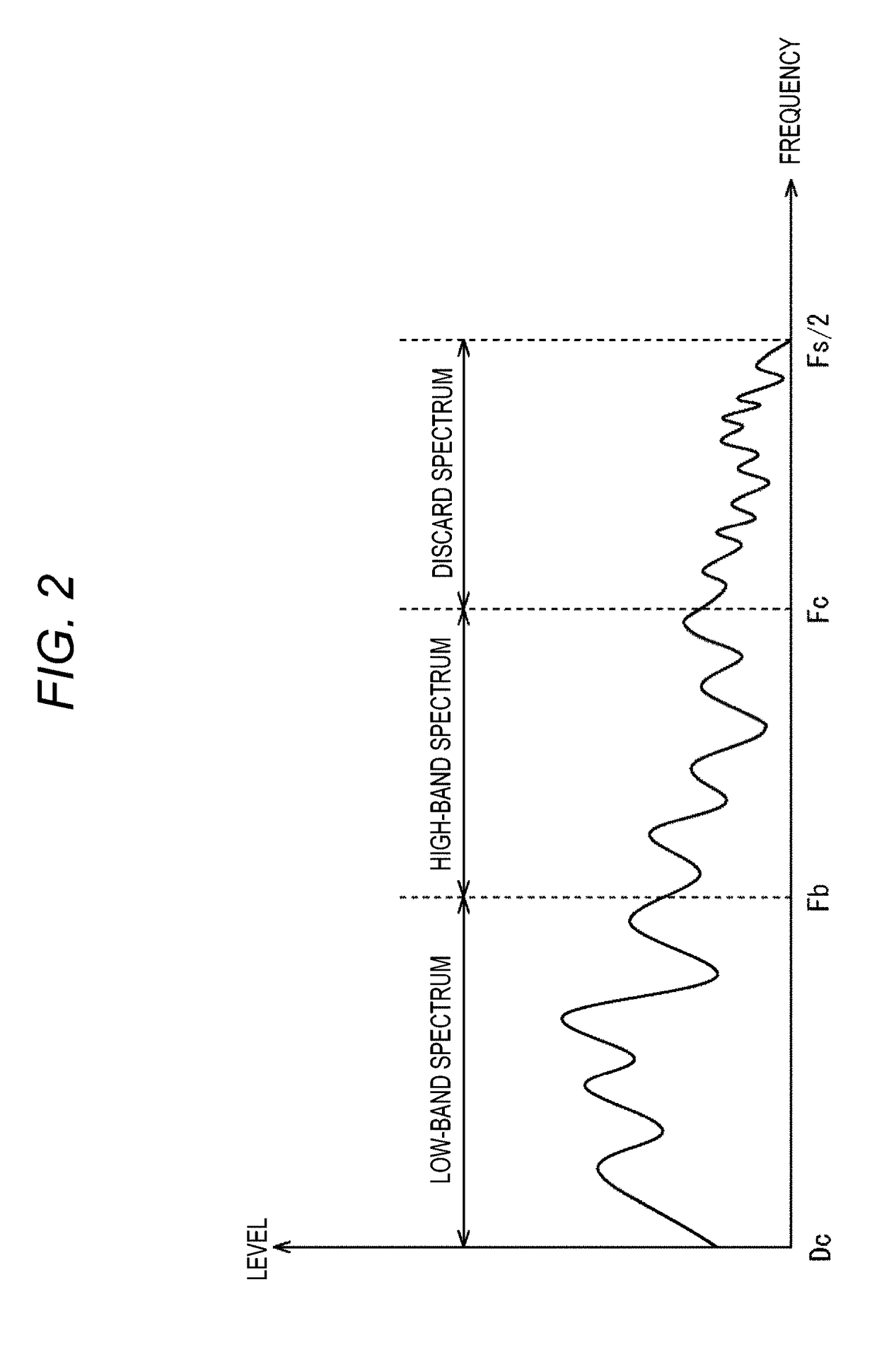
[0061]An input signal that is a time-series signal of a sampling frequency Fs [kHz] is supplied as the current audio signal to be encoded, to the MDCT unit 21.

[0062]The MDCT unit 21 performs MDCT as orthogonal transform, for example, on the supplied input signal, and obtains a spectrum from a frequency Dc [kHz] that is a DC component to a frequency Fs / 2 that is half the sampling frequency Fs.

[0063]It should be noted that, in the example case described below, MDCT is performed as o...

second embodiment

[0228]

[0229]In a case where the tonality of the low band of an input signal is high, the tonality of the high band of the input signal is normally likely to be also high. Therefore, in the encoding process described above, when both the low-band spectral feature quantity and the high-band spectral feature quantity are smaller than the threshold, the current input signal to be encoded has spectral characteristics exhibiting a high tonality.

[0230]However, as shown in FIG. 13, for example, there is an input signal having spectral characteristics that exhibit a high tonality in the low-band spectrum and a low tonality in the high-band spectrum, though such an input signal is not often generated. It should be noted that the ordinate axis in FIG. 13 indicates spectral value or level, and the abscissa axis indicates frequency.

[0231]In FIG. 13, a curve C61 represents the MDCT spectrum of the current input signal to be encoded. Specifically, in this MDCT spectrum, the portion from the freque...


PUM


Abstract

The present technology relates to an encoding device and a method, a decoding device and a method, and a program that enables acquisitions of high-quality sound even in a resource-poor setting.
A demultiplexer demultiplexes a supplied code string, to obtain the quantized low-band spectrum, the spectral characteristic code, and the quantized expansion coefficient(s). At this point, the code string includes a single quantized expansion coefficient or quantized expansion coefficients of the respective bands in the high band depending on the spectral characteristic code. A spectral inverse quantization unit obtains the low-band spectrum by inversely quantizing the quantized low-band spectrum. An expansion coefficient inverse quantization unit obtains the expansion coefficient(s) by inversely quantizing the quantized expansion coefficient(s). An expanded spectrum generation unit generates an expanded spectrum, in accordance with the low-band spectrum and the expansion coefficient(s) depending on the spectral characteristic code. An IMDCT unit generates a band-expanded time-series signal from the low-band spectrum and the expanded spectrum. The present technology can be applied to decoding devices.

Description

TECHNICAL FIELD[0001]The present technology relates to an encoding device and a method, a decoding device and a method, and a program. More particularly, the present technology relates to an encoding device and a method, a decoding device and a method, and a program that enable acquisitions of high-quality sound in a resource-poor setting.BACKGROUND ART[0002]There is a known coding technology that utilizes the concept of a band expansion for an audio signal (see Patent Document 1 and Patent Document 2, for example).[0003]By such a coding technology, a time-series signal that is input as an audio signal is divided into a low-band component and a high-band component. Conventional encoding is performed on the low-band signal, and the relationship between the low-band signal and the high-band signal, the features of the high-band signal, and the like are transmitted as additional information.[0004]Also, at the time of decoding, after the low-band signal is restored, an expanded-band sig...

Claims


Application Information

Patent Timeline
Patent Type & Authority Applications(United States)
IPC IPC(8): G10L19/02
CPCG10L19/0212G10L19/0204G10L19/22G10L19/24G10L21/038H03M7/30G10L21/0388G10L19/02
Inventor NISHIGORI, SHUICHIROSUZUKI, SHIRO
Owner SONY CORP
Why Eureka
Try Eureka