Vacuum cleaner

a vacuum cleaner and vacuum cleaner technology, applied in the field of vacuum cleaners, can solve the problems of difficult to directly discriminate an obstacle by a sensor, worse efficiency, etc., and achieve the effect of effectively avoiding objects and efficiently cleaning narrow spots

Active Publication Date: 2017-09-28
TOSHIBA LIFESTYLE PROD & SERVICES CORP
View PDF4 Cites 29 Cited by
  • Summary
  • Abstract
  • Description
  • Claims
  • Application Information

AI Technical Summary

Benefits of technology

[0007]An object of the invention is to provide a vacuum cleaner capable of more efficiently cleaning narrow spots while effectively avoiding objects.
[0008]The vacuum cleaner according to the embodiments includes a main casing, driving wheels, a cleaning unit, an object sensor, and a control unit. The driving wheels enable the main casing to travel on a cleaning-object surface. The cleaning unit cleans the cleaning-object surface. The object sensor is provided in the main casing and detects the presence or absence of an object within a specified distance in a plurality of directions on a forward side of the main casing. The control unit controls operation of the driving wheels based on detection of an object by the object sensor to thereby make the main casing autonomously travel. When an object is detected by the object sensor, the control unit controls the operation of the driving wheels so that the main casing is swung to an angle corresponding to a direction of the detected object to thereby make a side portion of the main casing face the object.

Problems solved by technology

However, sensors mounted on such vacuum cleaners are ordinarily infrared sensors, ultrasonic sensors and the like and so it is not easy to directly discriminate an obstacle by a sensor.
However, this action results in an unnecessary action as a cleaning action and moreover entering narrow spots surrounded by obstacles or escaping from narrow spots involves such scanning every time, leading to worse efficiency.

Method used


Image

  • Vacuum cleaner
  • Vacuum cleaner
  • Vacuum cleaner

Examples


Embodiment Construction

[0024]Hereinbelow, an embodiment will be described in terms of its constitution with reference to the accompanying drawings.

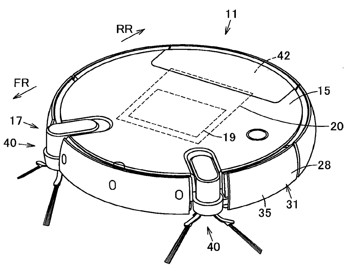
[0025]In FIGS. 6 to 9, reference sign 11 denotes a vacuum cleaner as an autonomous traveler. This vacuum cleaner 11 is provided as a vacuum cleaner device serving as an autonomous traveling device together with, for example, a charging device (charging stand) as an unshown station device containing a charging circuit.

[0026]The vacuum cleaner 11 is, in this embodiment, a so-called self-propelled robot cleaner (cleaning robot) that, while autonomously traveling (self-propelling) on a floor surface being a cleaning-object surface as a travel surface, cleans the floor surface. The vacuum cleaner 11 includes a hollow main casing 15, a traveling part 16 for making the main casing 15 travel on the floor surface, a cleaning unit 17 for cleaning dust and dirt on the floor surface and the like, a communication part 18 for communicating with an external device including a...


PUM


Abstract

A vacuum cleaner capable of more efficiently cleaning narrow spots while effectively avoiding an object. An object sensor provided in a main casing detects the presence or absence of an object within a specified distance in a plurality of directions on a forward side of the main casing. A control unit controls operation of driving wheels, based on detection of an object by the object sensor to thereby make the main casing autonomously travel. When an object is detected by the object sensor, the control unit controls the operation of the driving wheels, so that the main casing is swung to an angle corresponding to a direction of the detected object to thereby make a side portion of the main casing face the object.

Description

TECHNICAL FIELD[0001]Embodiments described herein relate generally to a vacuum cleaner which autonomously travels due to control of operation of its driving wheels based on detection of objects by an object detection means.BACKGROUND ART[0002]Conventionally, there is known a so-called autonomous-traveling type vacuum cleaner (cleaning robot) which autonomously travels on and cleans a cleaning-object surface while detecting an obstacle or the like by using, for example, a sensor or the like.[0003]Generally, since various obstacles of different shapes or placements are present on the cleaning-object surface, it is desirable that the cleaning-object surface can be cleaned without gaps as much as possible while those obstacles are effectively avoided. However, sensors mounted on such vacuum cleaners are ordinarily infrared sensors, ultrasonic sensors and the like and so it is not easy to directly discriminate an obstacle by a sensor.[0004]Accordingly, it is conceivable that, for example...

Claims


Application Information

Patent Timeline
Patent Type & Authority Applications(United States)
IPC IPC(8): A47L9/28G05D1/02A47L9/04G05D1/00A47L5/22A47L9/00
CPCA47L9/2852A47L2201/04A47L9/2826A47L9/009A47L9/0411A47L9/0477A47L9/0488A47L9/2894A47L9/2873A47L9/2884G05D1/0088G05D1/0242G05D1/0255A47L2201/022A47L5/22A47L9/28G05D2201/0203G05D1/0219
Inventor WATANABE, KOICHITOMIYAMA, TAKASHI
Owner TOSHIBA LIFESTYLE PROD & SERVICES CORP
Why Eureka
Try Eureka