Method and Apparatus for Multi-Line Fuel Delivery

a multi-line, fuel technology, applied in the direction of valve operating means/releasing devices, well accessories, liquid transfer devices, etc., can solve the problems of large number of potential failure points, and complex conventional systems, so as to prevent spills, avoid over-pressing of fuel lines, and adapt to any fuel tank neck size.

Active Publication Date: 2017-09-28
GRAVITY FUEL SYST LLC
View PDF4 Cites 139 Cited by
  • Summary
  • Abstract
  • Description
  • Claims
  • Application Information

AI Technical Summary

Benefits of technology

[0016]In a preferred embodiment, said gravity supply unit can be selectively raised to an elevation that is higher than a highest equipment fuel tank on location. The bulk tank can then feed a network of conduits, hoses or supply lines. All of the connections comprise a dry break, or a no-drip connection, in order to prevent any spills.
[0017]Additionally, by way of illustration, but not limitation, the fuel delivery assembly of the present invention utilizes a unique float valve assembly that is small enough to fit through a tank neck of a fuel tank. Said float valve assembly is mechanically operated and requires no fluid pressure to actuate and turn fuel flow on and off, thereby allowing said float valve assembly to operate in very low pressure environments. Further, said float valve not only turns on and off, but can also achieve equilibrium between fuel flow and fluid burn rate, thus keeping and maintaining a relatively steady flow of fuel instead of repetitive opening and closing.
[0018]The fuel delivery assembly of the present invention uses only the force of gravity to supply fuel from a bulk storage tank to separate fuel tanks of pumps, trucks and other equipment on a fracking location. As such, there is no risk of over pressuring fuel lines if a pump's internal or external pressure regulator fails. The fuel delivery assembly of the present invention does not requir

Problems solved by technology

However, in many cases such geologic formations have low permeability; due to such low permeability, hydrocarbon deposits may not flow from said geological formations at a desired flow rate.
Fracturing fluid is pumped into a wellbore at a rate that is sufficient to increase pressure at the target depth (which is generally determined by the location of the well casing perforations), and eventually, the target formation will not be able to absorb the fluid as quickly as it is being injected.
At this point, the pressure created exceeds that of the fracture gradient (pressure gradient) of the rock and causes the formation to crack or fracture.
Such convent

Method used


Image

  • Method and Apparatus for Multi-Line Fuel Delivery
  • Method and Apparatus for Multi-Line Fuel Delivery
  • Method and Apparatus for Multi-Line Fuel Delivery

Examples


Embodiment Construction

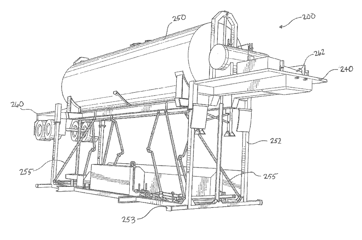
[0033]The present invention comprises a fluid delivery assembly for distributing fuel or other fluid in a safe and controlled manner to fuel tanks of one or more pump trucks or other equipment powered using internal combustion engines. For example, in a preferred embodiment, the fluid delivery assembly of the present invention can be used to deliver liquid fuel from a bulk storage tank to the individual fuel tanks of multiple trucks, high-pressure pumps and / or other powered equipment—sometimes referred to as a “spread”—situated on a location where fracking operations are performed.

[0034]In a preferred embodiment, the fuel delivery assembly of the present invention generally comprises a central bulk fluid tank (such as a bulk storage tank or container), ideally having sufficient capacity to store and supply fuel to at least one complete pump truck fleet used to conduct a conventional fracking operation. Additionally, said fluid delivery assembly further comprises a hydraulic power pa...


PUM


Abstract

A gravity-fed fuel delivery system is provided. A central storage tank holds fuel to re-supply a number of pump trucks or other mechanized equipment, such as on a hydraulic fracturing location, and can be selectively raised or lowered. Hoses or other conduits extend from the central storage tank to individual fuel tanks of the equipment to be refueled. Adapters allow connection of the distal end of each hose or conduit to an inlet opening of a fuel tank. A float valve assembly senses when fuel inside an individual fuel tank is below a predetermined level, thereby mechanically opening a valve assembly to permit fluid to flow from the central storage tank, through a conduit, through the float valve assembly and into the fuel tank.

Description

CROSS REFERENCES TO RELATED APPLICATIONS[0001]PRIORITY OF U.S. PROVISIONAL PATENT APPLICATION Ser. No. 62 / 313,866, FILED Mar. 28, 2016, U.S. PROVISIONAL PATENT APPLICATION Ser. No. 62 / 340,093, FILED May 23, 2016, AND U.S. PROVISIONAL PATENT APPLICATION Ser. No. 62 / 406,541, FILED Oct. 11, 2016, INCORPORATED HEREIN BY REFERENCE, IS HEREBY CLAIMED.STATEMENTS AS TO THE RIGHTS TO THE INVENTION MADE UNDER FEDERALLY SPONSORED RESEARCH AND DEVELOPMENT[0002]NONEBACKGROUND OF THE INVENTION[0003]Field of the Invention[0004]The present invention pertains to a fuel delivery assembly for delivering fuel in a controlled manner to equipment, including, but not limited to, hydraulic fracturing pumps and related equipment in the oil and gas industry. More particularly, the present invention pertains to a fuel delivery assembly for providing a gravity-fed fuel supply to hydraulic fracturing equipment in the oil and gas industry.[0005]Brief Description of the Prior Art[0006]Geological formations may co...

Claims


Application Information

Patent Timeline
IPC IPC(8): B67D7/36F16K31/26B67D7/84B67D7/04B67D7/78
CPCB67D7/365B67D7/04E21B43/26B67D7/845F16K31/265B67D7/78B67D7/0401B67D7/3218B67D7/74E21B43/2607
Inventor SCHMIDT, BRENNAN
Owner GRAVITY FUEL SYST LLC
Why Eureka
Try Eureka