Privacy lock mechanism

a technology for privacy doors and locks, applied in latching locks, keyhole guards, building locks, etc., can solve the problems of increasing the complexity and cost of lock devices, affecting the lock devices, damage and/or break of lock devices, etc., and achieve the effect of preventing the rotational displacement of the second chassis portion

Active Publication Date: 2017-09-28
SCHLAGE LOCK
View PDF8 Cites 3 Cited by
  • Summary
  • Abstract
  • Description
  • Claims
  • Application Information

AI Technical Summary

Benefits of technology

[0007]Another aspect of the present application is directed to a lock assembly that includes a first latch assembly portion having a first lever, a first chassis portion, and a first locking module portion. The first locking module portion has a locking shaft and a locking lug, the locking shaft having a cam protrusion, the slider body having a slider arm, the first chassis portion including a locking slot sized to receive selective insertion of at least a portion of the locking lug. The lock assembly further includes a second latch assembly portion having a second lever, a second chassis portion, and a second locking module portion. The second locking module has a cam body and a slider body, the slider body having a slider arm. The second chassis portion can include a retention slot sized to receive selective insertion of at least a portion of the slider arm. Further, the cam body is rotatably displaceable in a first rotational direction to effectuate rotational displacement of the cam protrusion in the first rotational direction when the slider body is linearly displaced from a slider unlocked position to a slider locked position. The rotational

Problems solved by technology

Accordingly, with the possible exception of an emergency release that is often of limited accessibility or the use of illicit means, operation of the lock device from the opposite side of the lock device generally does not include the ability to displace the lock mechanism between the locked and unlocked positions.
Yet, with such designs, torque exerted on the outside knob or lever is typically transmitted to a relatively weak central spindle, which may damage and/or break the lock device.
Further, attempts to resist or pr

Method used


Image

  • Privacy lock mechanism
  • Privacy lock mechanism
  • Privacy lock mechanism

Examples


Embodiment Construction

[0023]Certain terminology is used in the foregoing description for convenience and is not intended to be limiting. Words such as “upper,”“lower,”“top,”“bottom,”“first,” and “second” designate directions in the drawings to which reference is made. This terminology includes the words specifically noted above, derivatives thereof, and words of similar import. Additionally, the words “a” and “one” are defined as including one or more of the referenced item unless specifically noted. The phrase “at least one of” followed by a list of two or more items, such as “A, B or C,” means any individual one of A, B or C, as well as any combination thereof.

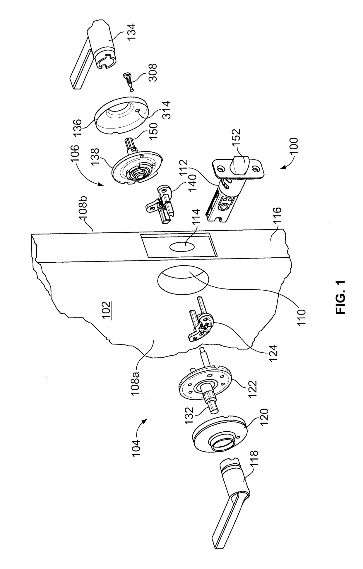
[0024]FIG. 1 illustrates an exploded view of a lock assembly 100 that is structured to be operably mounted or coupled to an entryway device 102, such as, for example, a door or gate, among other devices. The lock assembly 100 includes a first latch assembly portion 104 that is structured to extend from a first side 108a of the entryway device 102...


PUM


Abstract

A lock device that prevents operation of at least one chassis spindle from retracting a latch bolt, and which may provide auto-unlock features. Locking of the lock device can effectuate linear displacement of a slider body from an unlocked position to a locked position. Linear displacement of the slider body is translated into rotational displacement of a cam body that includes, or is coupled to, a locking shaft having a cam protrusion, thereby rotating the cam protrusion. As the cam protrusion rotates, the cam protrusion lifts a locking lug to a locked position wherein the locking lug prevents rotational displacement of a first chassis spindle. When in the locked position, a slider arm of the slider body can be positioned in a retention slot. Subsequent rotatable displacement of a second chassis spindle can effectuate displacement of the slider arm from the retention slot and facilitate unlocking of the lock device.

Description

CROSS-REFERENCE TO RELATED APPLICATIONS[0001]The present application claims the benefit of U.S. Provisional Patent Application No. 62 / 312,206 filed Mar. 23, 2016, and also claims the benefit of U.S. Provisional Patent Application No. 62 / 311,996 filed Mar. 23, 2016, the contents of each application incorporated herein by reference in their entirety.TECHNICAL FIELD[0002]Embodiments of the present application generally relate to locking mechanisms, and more particularly, but not exclusively, to locking mechanisms for privacy door locks.BACKGROUND[0003]Mechanical tubular lock devices may be utilized for a variety of different types of applications. For example, certain tubular lock devices may selectively control the ability to displace an entryway device, to which the lock device may be mounted or otherwise operably coupled, including, but not limited to, the displacement of a door or gate, relative to an entryway. Moreover, such lock devices may be used in connection with the entryway...

Claims


Application Information

Patent Timeline
IPC IPC(8): E05B13/00E05B55/00
CPCE05B55/005E05B13/004E05B63/0069E05C1/163E05B63/0056E05B63/0065
Inventor MURPHY, NATHANAEL S.MALENKOVIC, PETER
Owner SCHLAGE LOCK
Why Eureka
Try Eureka