Gas sensor manufacturing method and gas sensor manufacturing apparatus

Active Publication Date: 2017-09-28
NGK INSULATORS LTD
View PDF0 Cites 3 Cited by
  • Summary
  • Abstract
  • Description
  • Claims
  • Application Information

AI Technical Summary

Benefits of technology

The present invention provides a method for manufacturing a gas sensor that can prevent the occurrence of breakage failures within the sensor element, reducing the likelihood of defective products being generated. This is achieved by performing a second compression for hermetic sealing between the spaces located on one end side and the other end side of the sensor element inside of the tubular body, without using the element positioning member. This method effectively prevents the usage of assembled bodies that have breakage failures due to washer inclination or holding potential in the future.

Problems solved by technology

If the sensor element is inclined and comes in contact with the ceramic supporters at the time of the sealing, thereby being subjected to an action of a stress from the ceramic supporters, a crack may occur in a portion of the sensor element being in contact with the ceramic supporters in a process of manufacture or in use, or the sensor element may be broken at the contact portion.

Method used


Image

  • Gas sensor manufacturing method and gas sensor manufacturing apparatus
  • Gas sensor manufacturing method and gas sensor manufacturing apparatus
  • Gas sensor manufacturing method and gas sensor manufacturing apparatus

Examples


Embodiment Construction

[0055]

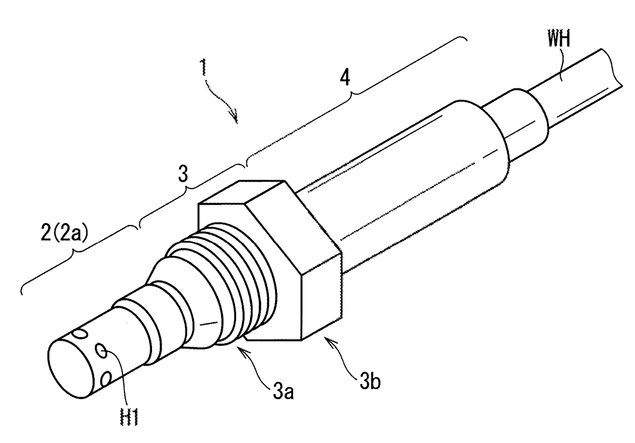
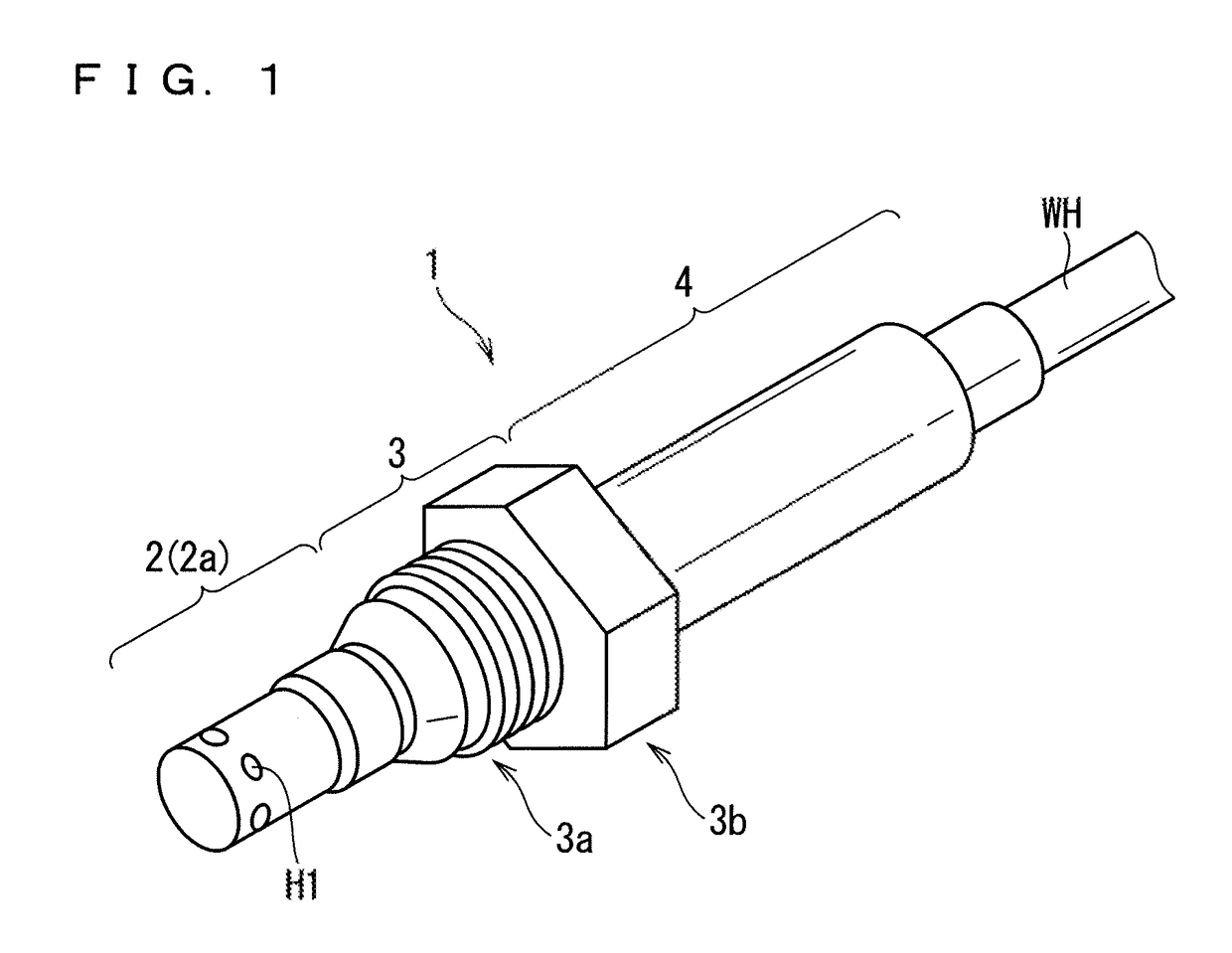
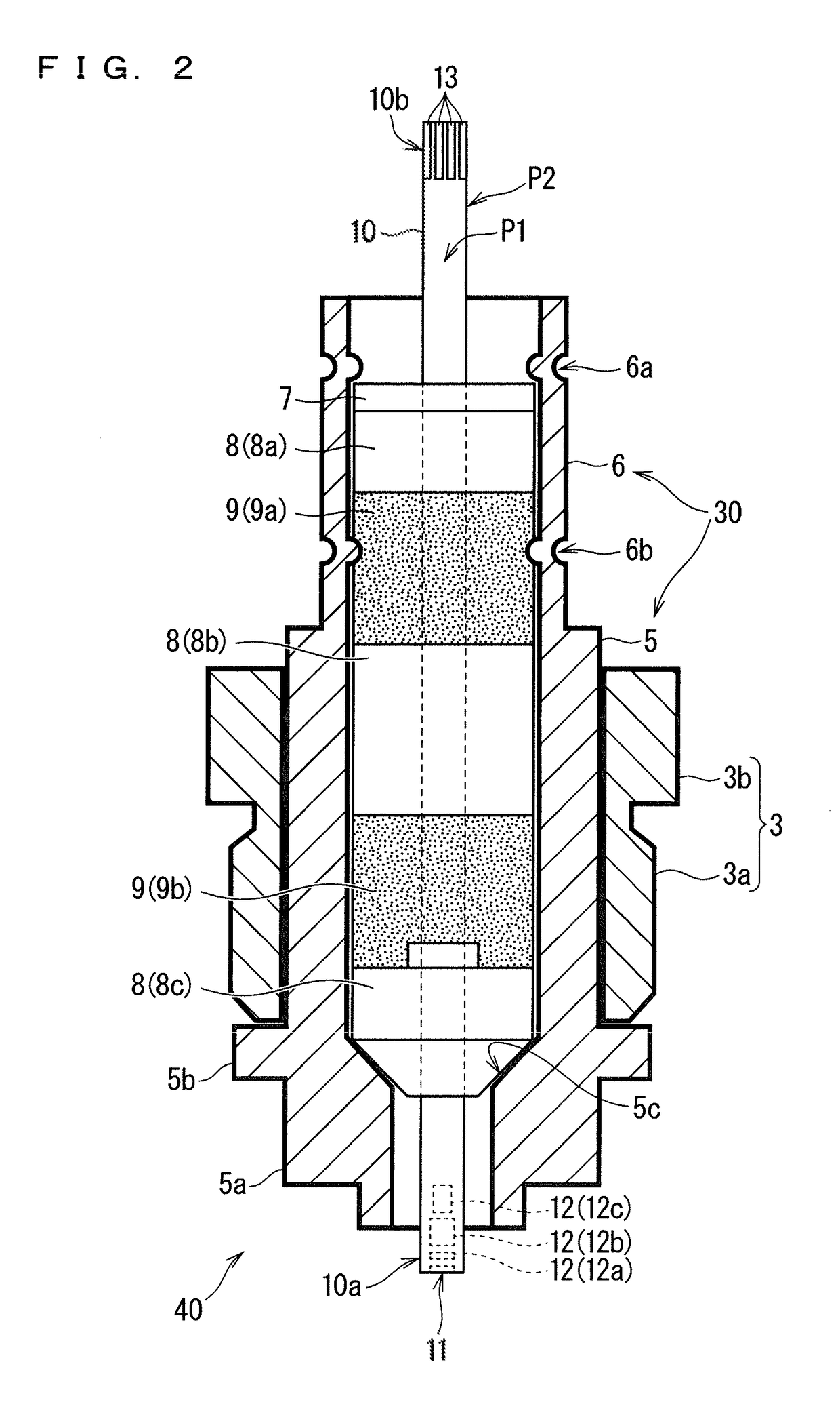
[0056]FIG. 1 is an external perspective view of a gas sensor (more specifically, its main body) 1 to be manufactured in this preferred embodiment. FIG. 2 is a partial cross-sectional view illustrating a main structure inside the gas sensor 1. In this preferred embodiment, the gas sensor 1 serves to detect a predetermined gas component (such as NOx) with a sensor element 10 (FIG. 2) included therein.

[0057]The sensor element 10 is an elongated columnar or thin-plate like member including, as a main constituent material, an oxygen-ion conductive solid electrolyte ceramic such as zirconia. The sensor element 10 has a configuration in which a gas inlet, an internal space, and the like are provided on a first tip portion 10a side and various electrodes and wiring patterns are provided on a surface and inside of an element body. In the sensor element 10, a detection gas introduced into the internal space is reduced or decomposed in the internal space, to thereby generate oxygen ions....


PUM

PropertyMeasurementUnit
Forceaaaaaaaaaa
Electrical resistanceaaaaaaaaaa
Heightaaaaaaaaaa

Abstract

Provided is a method for manufacturing a gas sensor which suppresses a defective product caused by a defective posture of a sensor element therein. The method includes a step of obtaining an assembled body constituting the gas sensor, including steps of: causing one end of the sensor element to come to abut to a positioning member for positioning the sensor element; and applying a first force to the annularly-mounted members including a powder compact annularly mounted to the sensor element under a state that the sensor element is positioned and thereby compressing the powder compact so as to fix the sensor element inside of the tubular body, and the compression is performed while constraining the sensor element in a predetermined constraining region in the other end side of the sensor element.

Description

BACKGROUND OF THE INVENTION[0001]Field of the Invention[0002]The present invention relates to a method for manufacturing a gas sensor including a ceramic sensor element.[0003]Description of the Background Art[0004]Conventionally, there have been well known gas sensors having sensor elements formed from an oxygen-ion conductive solid electrolyte ceramic, such as zirconia (ZrO2), as devices for determining the concentrations of predetermined gas components in measurement gas, such as combustion gasses and exhaust gasses in internal combustion engines such as automobile engines.[0005]Such gas sensors generally include a sensor element (detection element) with an elongated plate shape which is made of a ceramic, wherein the sensor element is secured by a plurality of ceramic supporters which are ceramic insulators and by powder compacts made of ceramics such as talc which are embedded between the ceramic supporters, in a hollow portion of a metal housing and a cylindrical inner tube sec...

Claims


Application Information

Patent Timeline
IPC IPC(8): G01N27/407G01N27/406G01N33/00
CPCG01N27/4078G01N27/4067G01N33/0037G01N27/4175Y10T29/49829Y10T29/49934Y10T29/53187Y02A50/20
Inventor ISAKA, KENJIEGAWA, KOJIIKOMA, NOBUKAZU
Owner NGK INSULATORS LTD
Why Eureka
Try Eureka