Plasma torch with electrode wear detection system

Active Publication Date: 2011-02-24
THE ESAB GROUP
View PDF30 Cites 8 Cited by
  • Summary
  • Abstract
  • Description
  • Claims
  • Application Information

AI Technical Summary

Benefits of technology

[0007]A plasma arc torch, electrode, and method are therefore provided for allowing a user to detect the wear on an electrode. In particular, a plasma arc torch is prov

Problems solved by technology

Users of plasma torches (blow-back and blow-forward) are often required to replace the electrode used in the torch as the electrode experiences wear during plasma torch operations.

Method used


Image

  • Plasma torch with electrode wear detection system
  • Plasma torch with electrode wear detection system
  • Plasma torch with electrode wear detection system

Examples


Example

[0038]Embodiments of the present invention now will be described more fully hereinafter with reference to the accompanying drawings, in which some but not all embodiments are shown. Indeed, the invention may be embodied in many different forms and should not be construed as limited to the embodiments set forth herein; rather, these embodiments are provided so that this disclosure will satisfy applicable legal requirements. Like reference numerals refer to like elements throughout.

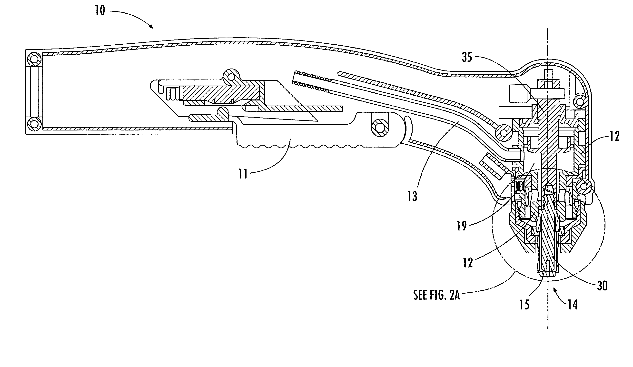
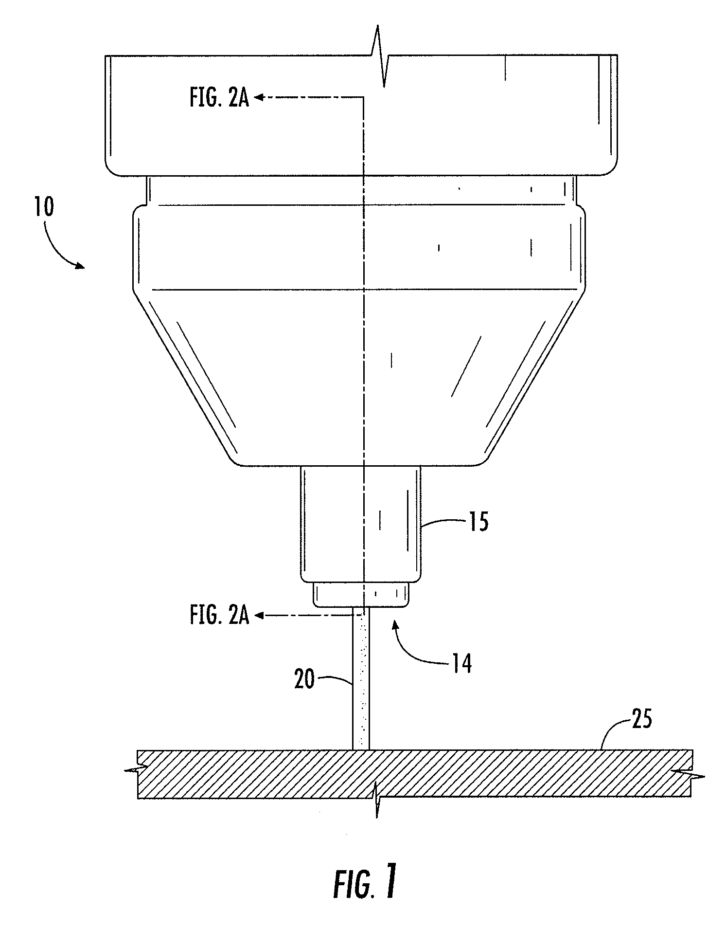
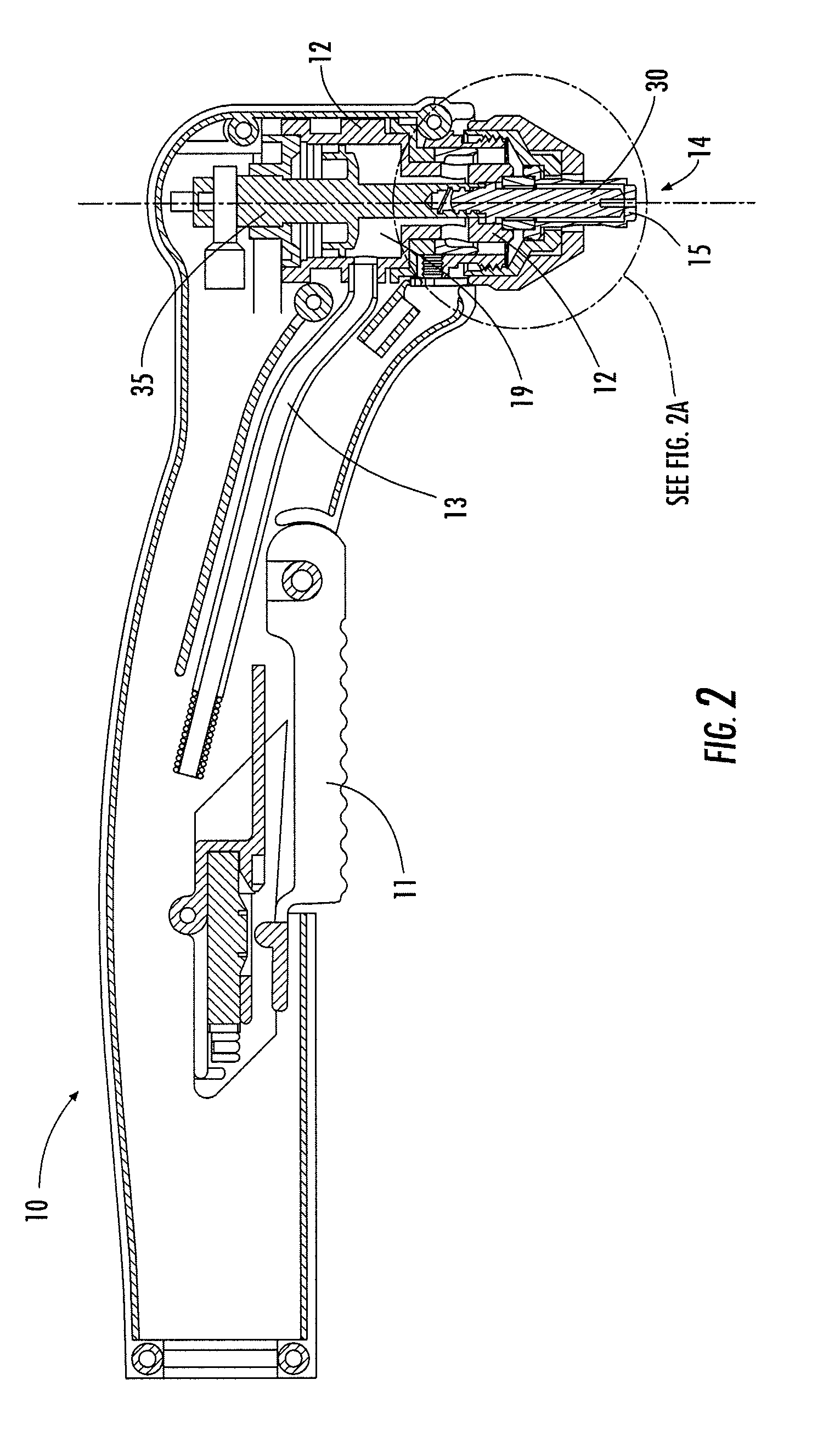
[0039]A blow-back type plasma torch 10 in accordance with embodiments of the present invention is shown in FIGS. 1 and 2. The torch 10 includes a main torch body 12 and an electrically conductive nozzle 15 fixed with respect to the body 12 at an operational end 14 of the torch 10. As described in greater detail below, the nozzle 15 is configured to direct a high velocity stream of plasma gas 20 towards a work piece 25 that is to be cut or marked. In this way, an electric arc that is initiated within the tor...


PUM

PropertyMeasurementUnit
Lengthaaaaaaaaaa
Poweraaaaaaaaaa
Electric potential / voltageaaaaaaaaaa

Abstract

A plasma arc torch is provided that includes a wear stop designed to detect wear of an electrode and prevent the use of the electrode once the electrode has experienced a certain amount of wear. Either the electrode or the nozzle is movable with respect to the main torch body, and the movable component defines a projection. The wear stop is positioned a predetermined distance from a nozzle of the torch, such that prior to experiencing an excessive amount of wear, the electrode is able to contact the nozzle and initiate a pilot arc for starting a torch operation. Once the length of the electrode becomes shorter than a predetermined length due to wear, the projection of the electrode engages the wear stop, and the wear stop prevents the electrode from contacting the nozzle. In this way, an electrode that is excessively worn cannot be used in subsequent torch operations.

Description

BACKGROUND[0001]The present application relates to plasma arc torches, particularly plasma arc torches of the so-called blow-back type.[0002]Plasma torches are commonly used for cutting or marking metal work pieces. In general, plasma torches use an electrode to generate an electric arc within the torch. A high velocity gas is flowed through the torch, and the electric arc ionizes the gas, creating a plasma. The high velocity stream of ionized gas, or plasma, is delivered through a nozzle of the torch towards the work piece that is to be cut. The plasma serves to conduct electricity from the torch to the work piece. In this way, the plasma heats the work piece, melting the metal in the location of the cut, and mechanically blows the molten metal away to form the cut.[0003]In blow-back torches, the nozzle is generally fixed with respect to the torch body, and the electrode is displaceable with respect to the nozzle. Initially, the electrode is in contact with the nozzle. When the blo...

Claims


Application Information

Patent Timeline
IPC IPC(8): B23K10/00
CPCB23K10/006H05H2001/3494H05H2001/3489H05H1/34H05H1/3489H05H1/3494H05H1/3423
Inventor GRIFFIN, DAVID C.
Owner THE ESAB GROUP
Why Eureka
Try Eureka