Eye-Tracking System and Method Therefor

Active Publication Date: 2017-09-28
ADHAWK MICROSYST
View PDF3 Cites 28 Cited by
  • Summary
  • Abstract
  • Description
  • Claims
  • Application Information

AI Technical Summary

Benefits of technology

The patent is about a method of estimating the position of the cornea in an eye scan. This is important because the cornea is the part of the eye that helps to shape the input beam of a laser system. The method involves scanning the beam back and forth along a straight line and using a control method to maximize the signal from a detector. The result is a more accurate estimate of the cornea's position.

Problems solved by technology

Unfortunately, conventional eye-trackers are slow, bulky, invasive, and / or restrictive for the user.
This makes them difficult, if not impossible to use in many of the applications discussed above.
In addition, conventional systems generally require cameras and imaging processing software.
As a result, they tend to be expensive, slow, and power hungry.
Furthermore, they typically exhibit significant lag between eye movement and measured eye position, which degrades the user experience in VR applications.
It is possible to improve the resolution and speed of such eye tracking systems but, to date, these improvements have come at the expense of user mobility and added system cost.
Eye coils mounted directly on the eye have been used to track eye position with high accuracy; however, they require operation within a magnetic field, which restricts the applications in which they can be used.
Further, since they are placed directly on the eyeball, they can only be used for limited times due to eye safety and vision impairment issues.
Electro-oculograms enable the position of the cornea through closed eyelids; however, they are subject to blink artifacts and signal noise.
In addition, they are relatively inaccurate.
As a result, electro-oculograms are relatively unattractive in many applications.
Unfortunately, such limbal-tracking systems are cumbersome, difficult to align and calibrate, and have poor sensitivity unless used at short range.
Unfortunately, such eye-tracking systems are slow, bulky, restrictive for the user, and expensive.
Wearable systems are bulky and heavy, making them quite uncomfortable for extended use.
Remote systems require careful positioning and alignment, which can be easily disrupted during operation.
Further, video capture is difficult to perform tracking through spectacles due to front surface reflections.
Unfortunately, an image of the eye surface must still be captured and analyzed via image processing to estimate eye position.
As a result, while such systems typically require less computational complexity than video-based eye-trackers, they still demand significant computational and energy resources.

Method used


Image

  • Eye-Tracking System and Method Therefor
  • Eye-Tracking System and Method Therefor
  • Eye-Tracking System and Method Therefor

Examples


Embodiment Construction

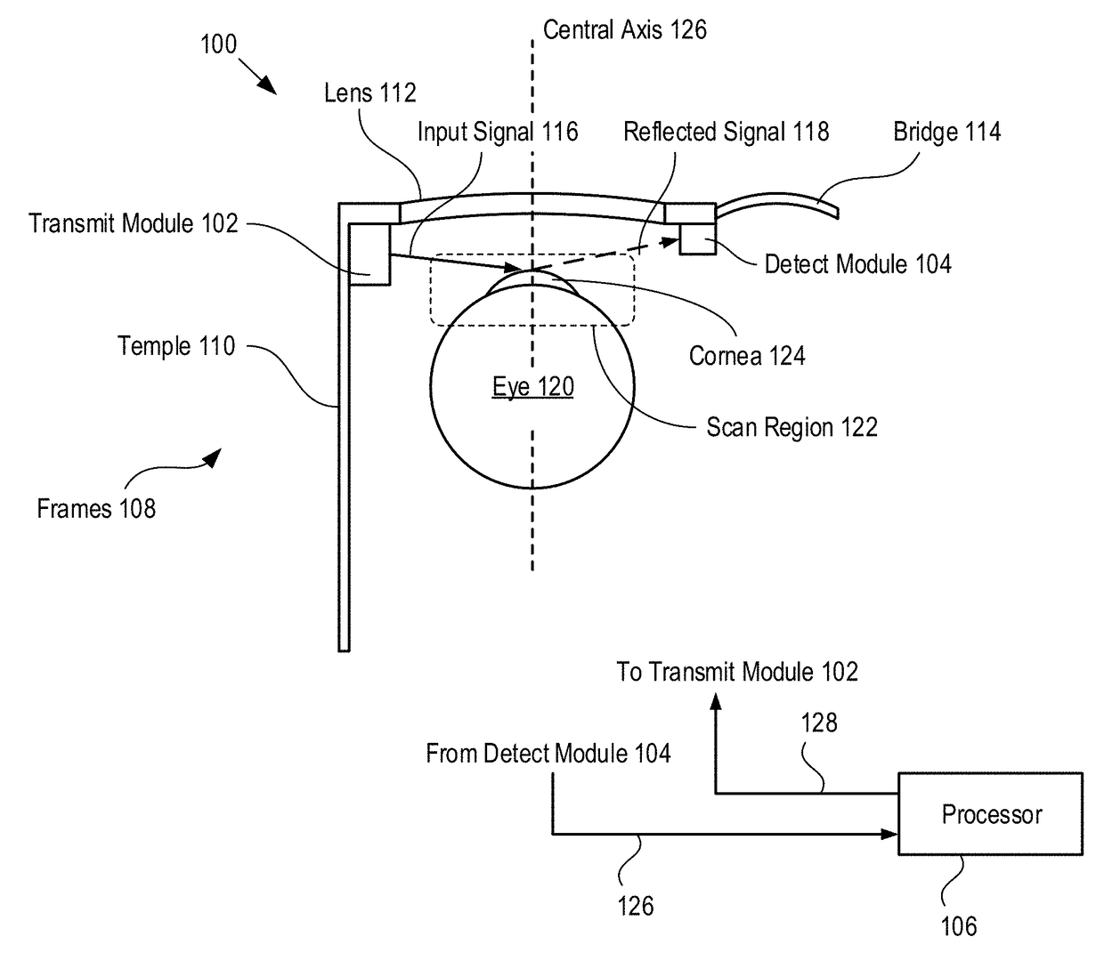
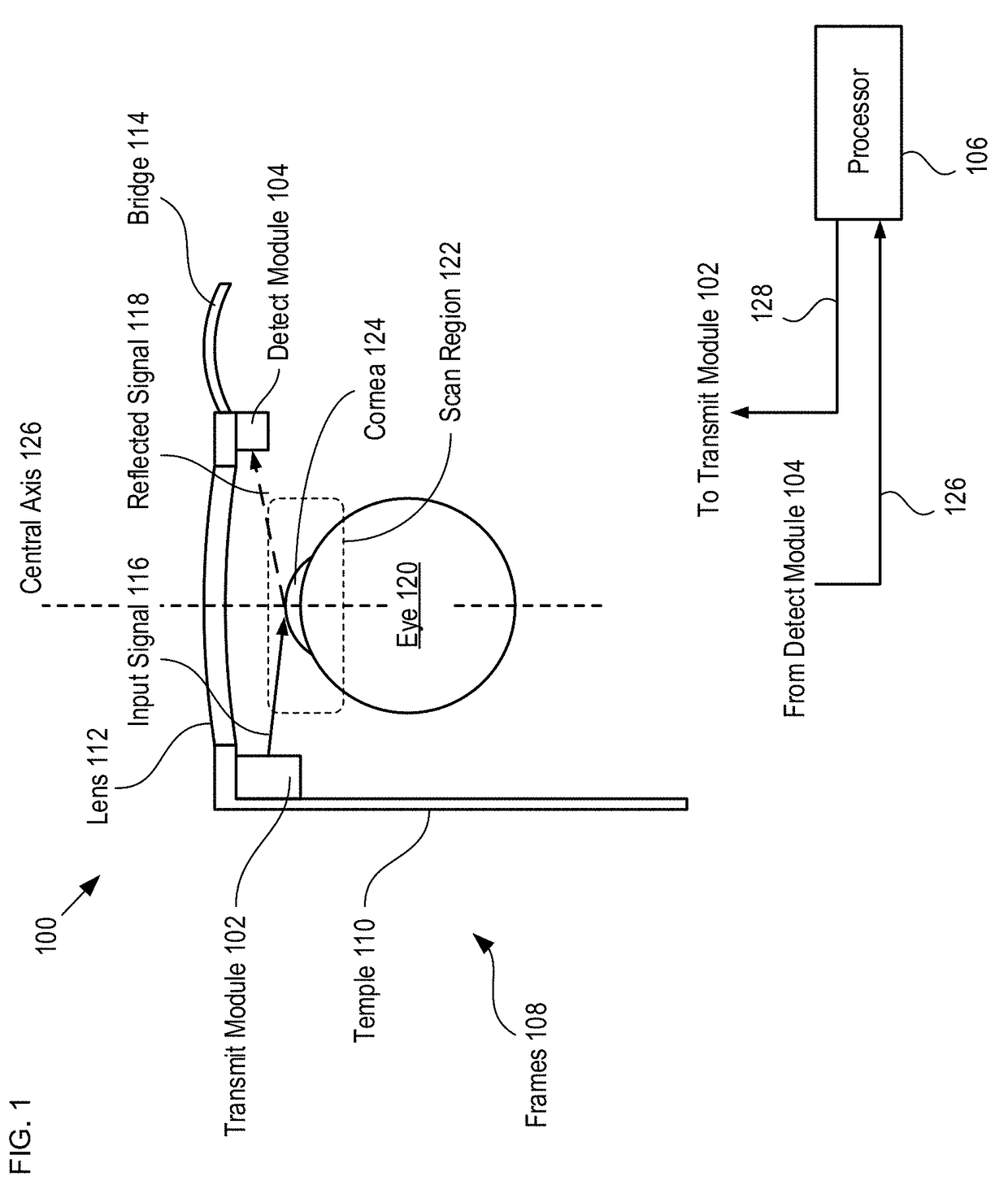
[0048]FIG. 1 depicts a schematic drawing of an eye-tracking system in accordance with an illustrative embodiment of the present invention. System 100 includes transmit module 102, detect module 104, and processor 106. Transmit module 102 and detect module 104 are arranged on a rigid support in a fixed orientation relative to one eye of a test subject. System 100 enables tracking of a surface feature (e.g., cornea 124) within a two-dimensional region of an eye during typical test subject behavior (e.g., reading, viewing a computer screen, watching television, monitoring a scene, etc.), and estimating the corneal vector of the eye based on the location of the surface feature. For the purposes of this Specification, including the appended claims, the “corneal vector” of an eye is defined as the gaze direction of the eye, which is indicated by a vector extending outward perpendicularly from the center of the pupil of an eye.

[0049]Transmit module 102 is a sub-system for providing an opti...


PUM


Abstract

A system for tracking eye location is disclosed. Systems in accordance with the present invention include a scanner for sweeping a first optical signal across the surface of an eye, a detector for detecting a second optical signal reflected from the eye, and a detection circuit for determining a maximum intensity in the second optical signal. In operation, the scanner sweeps the first optical signal over the surface of the eye while the detection circuitry determines a plurality of intensity maxima in the second optical signal. The time between the intensity maxima during the sweep is indicative of the location of the cornea within the eye surface.

Description

CROSS REFERENCE TO RELATED APPLICATIONS[0001]This application claims the benefit of U.S. Provisional Patent Application Ser. No. 62 / 345,926 and is a continuation-in-part of U.S. patent application Ser. No. 14 / 966,733 filed 11-Dec.-2015 which claims the benefit of U.S. Provisional Application Ser. No. 62 / 090,705, filed Dec. 11, 2014, entitled “Electro-Thermo-Mechanical Optical Scanner Suitable for Display, Imaging, or Object Tracking Applications,” (Attorney Docket 3001-004PR2), U.S. Provisional Application Ser. No. 62 / 181,276, filed Jun. 18, 2015, entitled “Near-Eye Display and Method Therefor,” (Attorney Docket 3001-004PR3), and U.S. Provisional Application Ser. No. 62 / 266,020, filed Dec. 11, 2015, entitled “System for Tracking Eye Position and Method Therefor,” (Attorney Docket 3001-004PR4), each of which is incorporated herein by reference as if set forth at length herein. If there are any contradictions or inconsistencies in language between this application and one or more of t...

Claims


Application Information

Patent Timeline
IPC IPC(8): G02B27/00G01P3/36G01B11/00G02B26/08
CPCG02B27/0093G01B11/002G01P3/36G02B26/0833A61B3/113A61B3/15G02B26/0866G02B26/101
Inventor SARKAR, NILADRI
Owner ADHAWK MICROSYST
Why Eureka
Try Eureka