Image forming apparatus

a technology of forming apparatus and forming tube, which is applied in the direction of electrographic process apparatus, instruments, optics, etc., can solve the problems of preventing the intended image from being obtained, the image density of the image is not uniform, etc., and achieves the effect of increasing the tinge selection range and increasing the amount of toner

Active Publication Date: 2017-09-28
CANON KK
View PDF7 Cites 11 Cited by
  • Summary
  • Abstract
  • Description
  • Claims
  • Application Information

AI Technical Summary

Benefits of technology

[0006]As described above, Japanese Patent Application Laid-open No. H8-227222 and Japanese Patent Application Laid-open No. 2013-210489 enable a tinge selection range to be increased and high-density printing to be performed by increasing a toner supply amount from a developing roller to a photosensitive drum. However, when an increase in a tinge selection range and high-density output as described in Japanese Patent Application Laid-open No. H8-227222 and Japanese Patent Application Laid-open No. 2013-210489 are consecutively performed in addition to normal printing operations, consumption of toner of the developing roller is accelerated as the toner is developed onto the photosensitive drum and a toner supply amount to the developing roller itself may run short. It is found that a shortage of the toner supply amount to the developing roller may result in an image containing image density non-uniformity and tinge variations and may prevent an intended image from being obtained.

Problems solved by technology

It is found that a shortage of the toner supply amount to the developing roller may result in an image containing image density non-uniformity and tinge variations and may prevent an intended image from being obtained.

Method used


Image

  • Image forming apparatus
  • Image forming apparatus
  • Image forming apparatus

Examples


first embodiment

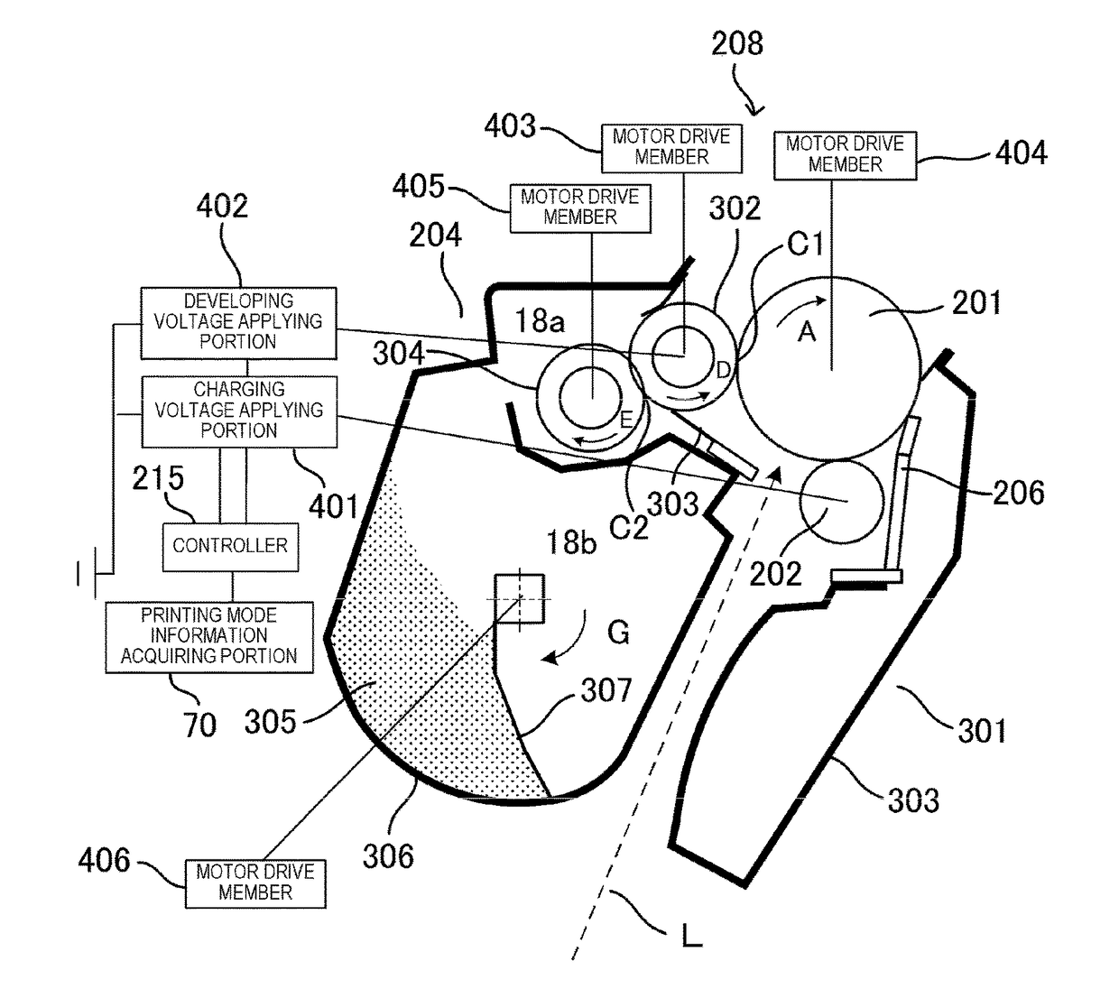
[0042]An image forming apparatus according to the present embodiment has two image formation modes: an image formation mode A for obtaining normal image density; and an image formation mode B for obtaining high density or increasing a tinge selection range by changing a peripheral velocity ratio between a photosensitive drum as an image bearing member and a developing roller as a developer bearing member. Each image formation mode has a different ratio of rotational speed (a peripheral velocity ratio) between a photosensitive drum and a developing roller particularly under a condition of forming a solid black image. In the image formation mode A, with respect to a development contrast formed by an electrostatic latent image formed on the photosensitive drum and a developing bias applied to the developing roller, all of the toner on the developing roller is developed onto the photosensitive drum. In the image formation mode B, the peripheral velocity ratio between the photosensitive ...

second embodiment

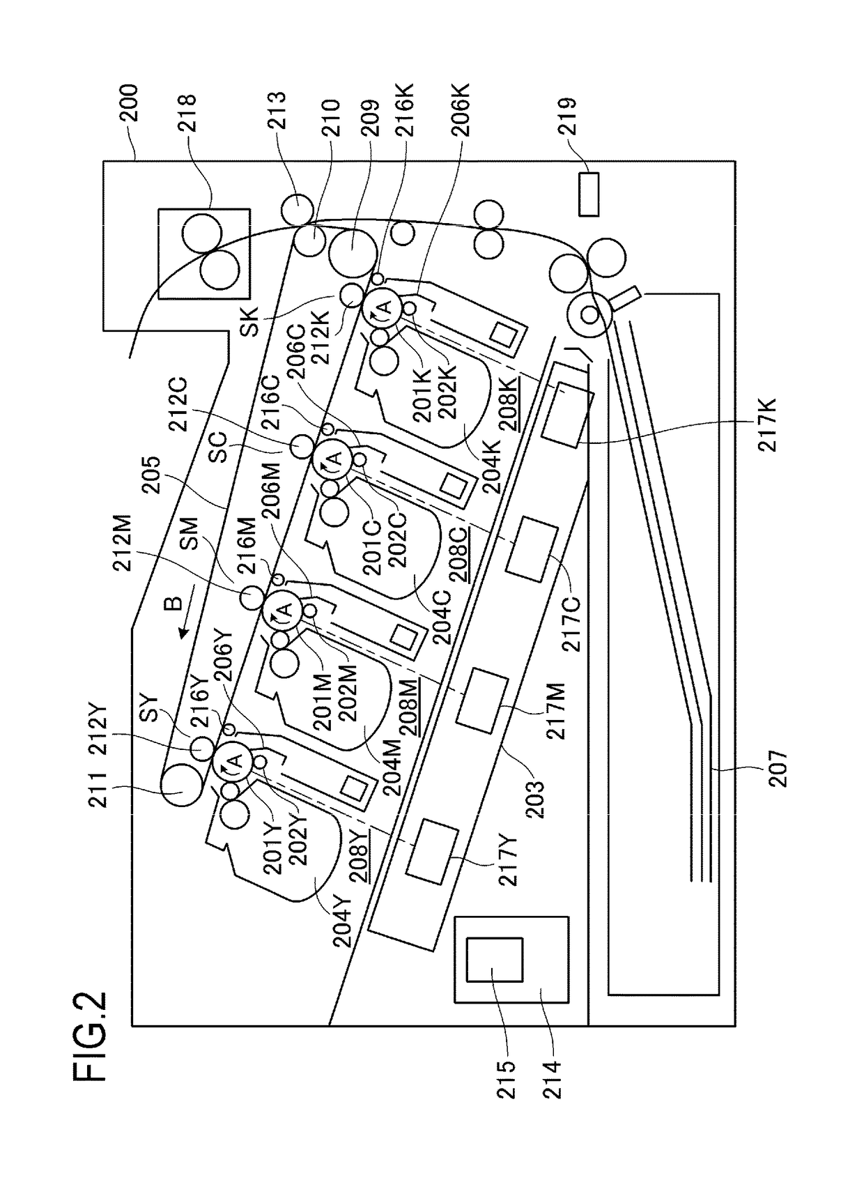
[0078]In the first embodiment described above, when performing a high-density mode, an operating condition which enables toner to remain on a developing roller even during printing of a high printing pattern such as solid black is adopted to realize stabilization of density and tinge while maintaining supplying performance of toner to the developing roller. A second embodiment of the present invention is configured such that, when an electrified charge amount of toner changes due to a change in the toner accompanying environmental conditions or specifications, peripheral velocity ratio control corresponding to the change is performed so that similar effects are obtained regardless of changes in conditions and the like. Specifically, an image forming apparatus according to the second embodiment includes a sensor 219 as detecting means configured to detect temperature and humidity (refer to FIG. 2). In addition, a CPU 315 assumes a low temperature, low humidity environment when the te...

third embodiment

[0086]FIG. 7 is a schematic sectional view of an image forming apparatus according to a third embodiment of the present invention. The image forming apparatus 200 according to the third embodiment includes, in addition to the configuration of the image forming apparatus according to the first embodiment, a recording material type detection sensor 220 which detects a width of the recording material 207 in a sub-scanning direction and a recording material type detection sensor 221 which detects a width of the recording material 207 in a main scanning direction. In the third embodiment, only differences from the first and second embodiments will be described. Matters not described in the third embodiment are similar to those described in the first and second embodiments.

[0087]FIG. 8 is a block diagram showing driving and high-voltage control of the photosensitive drum 201 and the developing roller 302 of the image forming apparatus according to the third embodiment. In FIG. 8, signals ...


PUM


Abstract

When, in a state where a developer borne by a developer bearing member is sandwiched by an opposing portion of an image bearing member and the developer bearing member, C denotes capacitance between the image bearing member and the developer bearing member, ΔV denotes a development contrast, Q/S denotes a charge amount per unit area of the developer borne by the developer bearing member, and Δv denotes a peripheral velocity ratio which is a ratio of a peripheral velocity of the developer bearing member to a peripheral velocity of the image bearing member, a first peripheral velocity ratio is set so that |Q/S×Δv|≦|C×ΔV| is satisfied, and a second peripheral velocity ratio which is larger than the first peripheral velocity ratio is set so that |Q/S×Δv|>|C×ΔV| is satisfied.

Description

BACKGROUND OF THE INVENTION[0001]Field of the Invention[0002]The present invention relates to an image forming apparatus using an electrophotographic system.[0003]Description of the Related Art[0004]Conventionally, as an image forming apparatus such as a laser beam printer, an image forming apparatus is known which adopts an in-line color system and which is constituted by a plurality of image forming stations in which a photosensitive drum as an image bearing member is arranged in plurality in a rotation direction of an intermediate transfer member. In the image forming apparatus, an electrostatic latent image created on the photosensitive drum in each of the plurality of image forming stations is developed into a toner image by developing means, and the resultant is primarily transferred to the intermediate transfer member. By similarly repeating primary transfers in the plurality of image forming stations in this step, a full-color toner image is formed on the intermediate transf...

Claims


Application Information

Patent Timeline
Patent Type & Authority Applications(United States)
IPC IPC(8): G03G15/06G03G15/08
CPCG03G15/065G03G15/0266G03G15/0856G03G15/5008G03G15/5037G03G15/0898G03G15/0815
Inventor NAITO, NORIHITOSHINDO, GOMOCHIZUKI, MASATAKA
Owner CANON KK
Why Eureka
Try Eureka