Liquid tank, atomizer and electronic cigarette having same

a technology of electronic cigarettes and liquid tanks, applied in the field of electronic cigarettes, can solve problems such as unsatisfactory atomization effects of atomizers

Active Publication Date: 2017-10-05
SHENZHEN FIRST UNION TECH CO LTD
View PDF5 Cites 60 Cited by
  • Summary
  • Abstract
  • Description
  • Claims
  • Application Information

AI Technical Summary

Benefits of technology

[0005]An exemplary liquid tank for an atomizer includes a bottom part, a liquid outlet, a first air inlet, a first porous liquid blocking element, and a top part. The bottom part has a first end and an opposite second end, and defines a liquid chamber for containing tobacco liquid. The liquid outlet is defined in the second end. The first air inlet is defined in the first end, so that external air can enter the liquid chamber

Problems solved by technology

Therefore, an atomization effect of

Method used


Image

  • Liquid tank, atomizer and electronic cigarette having same
  • Liquid tank, atomizer and electronic cigarette having same
  • Liquid tank, atomizer and electronic cigarette having same

Examples


Embodiment Construction

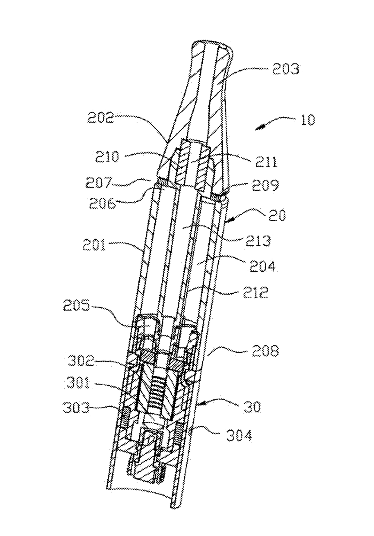
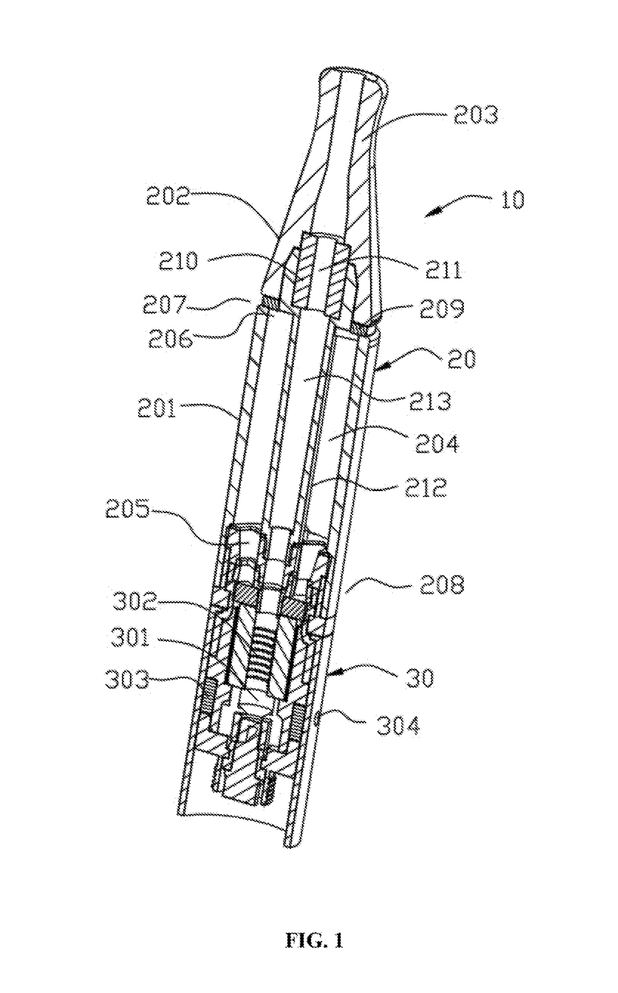
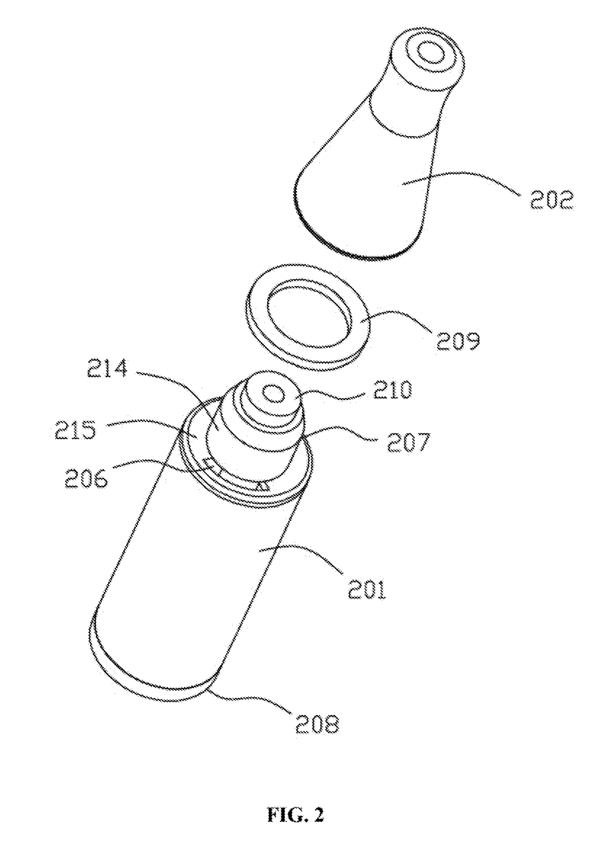
[0013]It will be appreciated that for simplicity and clarity of illustration, where appropriate, reference numerals have been repeated among the different figures to indicate corresponding or analogous elements. In addition, numerous specific details are set forth in order to provide a thorough understanding of the embodiments described herein. However, it will be understood by those of ordinary skill in the art that the embodiments described herein can be practiced without these specific details. In other instances, methods, procedures and components have not been described in detail so as not to obscure the related relevant feature being described. Also, the description is not to be considered as limiting the scope of the embodiments described herein. The drawings are not necessarily to scale and the proportions of certain parts have been exaggerated to better illustrate details and features of the present disclosure.

[0014]The disclosure is illustrated by way of example and not by...


PUM


Abstract

An exemplary liquid tank for an atomizer includes a bottom part, a liquid outlet, a first air inlet, a first porous liquid blocking element, and a top part. The bottom part has a first end and an opposite second end, and defines a liquid chamber for containing tobacco liquid. The liquid outlet is defined in the second end. The first air inlet is defined in the first end, so that external air can enter the liquid chamber via the first air inlet. The first porous liquid blocking element covers the first air inlet. The first porous liquid blocking element is capable of preventing the tobacco liquid in the liquid chamber from flowing out via the first air inlet, and allows air to pass through. The top part is detachably connected to the first end. The top part and the bottom part cooperatively clamp the first liquid blocking element therebetween.

Description

TECHNICAL FIELD[0001]The present invention relates to electronic cigarettes, and particularly to a liquid tank, an atomizer, and an electronic cigarette using same.BACKGROUND ART[0002]A typical atomizer includes an atomizing unit, and a liquid tank connected to the atomizing unit. The liquid tank defines a liquid outlet at an end connecting with the atomizing unit. Tobacco liquid stored in the liquid tank flows into the atomizing unit via the liquid outlet, so that the atomizing unit atomizes the tobacco liquid.[0003]However, external air goes into the liquid tank also through the liquid outlet. Accordingly, a negative pressure may exist in the liquid tank, and thus, the tobacco liquid may flow out unsmoothly. Therefore, an atomization effect of the atomizer may be unsatisfactory.[0004]What are needed, therefore, are a liquid tank, an atomizer, and an electronic cigarette using same, which can overcome the above shortcomings.SUMMARY[0005]An exemplary liquid tank for an atomizer incl...

Claims


Application Information

Patent Timeline
IPC IPC(8): A61M11/04A24F47/00A61M15/00
CPCA61M11/041A61M15/06A24F47/006A61M15/0001A61M11/042A24F40/40A24F40/10A24F40/42
Inventor LI, YONGHAIXU, ZHONGLIWU, RENJIN
Owner SHENZHEN FIRST UNION TECH CO LTD
Why Eureka
Try Eureka