
Mobile fluid storage tank

Inactive Publication Date: 2015-04-30
THIESSEN LONNY
View PDF14 Cites 46 Cited by
  • Summary
  • Abstract
  • Description
  • Claims
  • Application Information

AI Technical Summary

Benefits of technology

The patent describes a mobile tank for storing fluids that can be attached to a vehicle. The tank is designed to meet legal weight restrictions for axles while still being easy to transport. The goal is to make the tank as long and wide as possible, while keeping it tall and light. The technical effect is to create a practical and safe tank that can be easily moved around and used in various applications.

Problems solved by technology

On the other hand, the same industry also produces millions of cubic meters of water that is contaminated and requires storage, costly treatment and disposal.
However, these mobile tanks are limited in size.

Method used


Image

  • Mobile fluid storage tank
  • Mobile fluid storage tank
  • Mobile fluid storage tank

Examples


Embodiment Construction

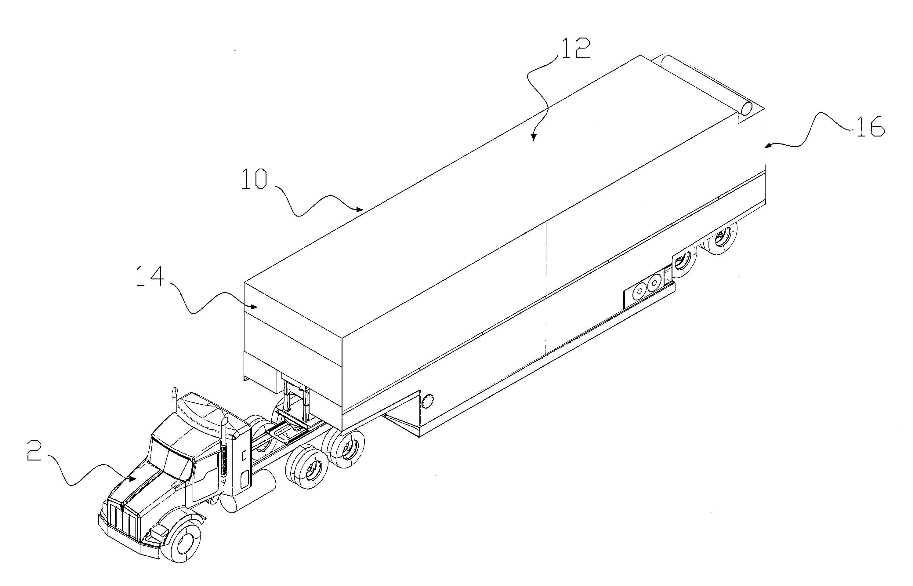
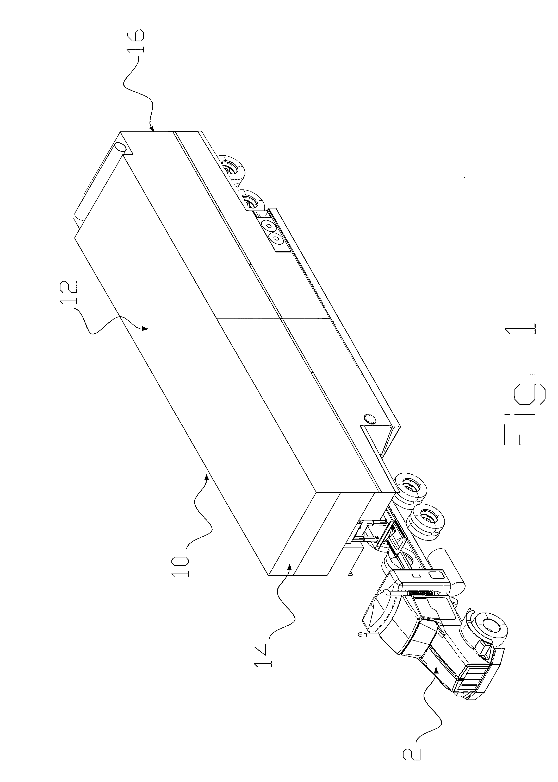
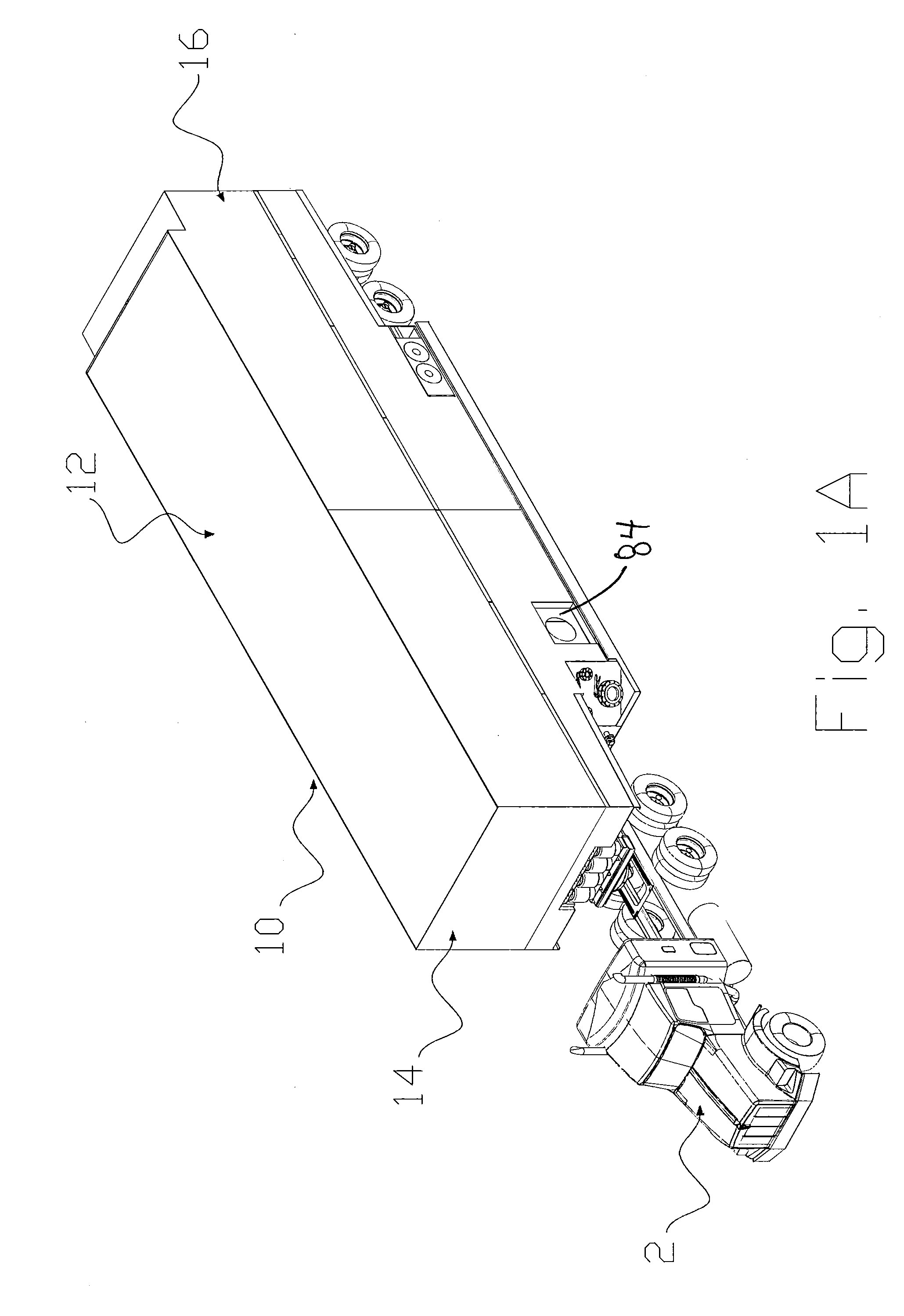
[0048]The preferred embodiment of a mobile storage tank assembly 10 according to the present invention is shown in FIG. 1 connected to a truck 2 and is shown in FIGS. 2-5 on its own, with the truck 2 disconnected from the hitching device 5. An alternative embodiment is shown in FIG. 1A.

[0049]Storage tank 10 has a top surface 12, a front wall 14, a rear wall 16, a pair of side walls 18 and a bottom 20 forming an enclosure within which liquids can be stored and transported. The bottom 20 has a front portion 22, a mid portion 24 and a rear portion 26, the front and rear portions 22, 26 being elevated above the level of the mid portion 24.

[0050]Construction of the mobile storage tank 10 will be described in more detail with reference to FIGS. 6-8. Typically mobile water tanks are designed to be round with a front to back frame in order to minimize bending and to provide longitudinal structural strength. However, in a mobile design this severely limits the volume available and increases ...


PUM

PropertyMeasurementUnit
Volumeaaaaaaaaaa
Temperatureaaaaaaaaaa
Lengthaaaaaaaaaa

Abstract

A mobile fluid storage tank for the use and storage of fluids comprising a unibody construction.

Description

FIELD OF THE INVENTION[0001]The present invention relates to a mobile fluid storage tank for the use and storage of fluids.BACKGROUND OF THE INVENTION[0002]The oil and gas industry requires and produces large volumes of fluids. For example, multiple millions of cubic meters of fresh water are consumed every year. This clean water is used directly in exploration, formation, modification / pre-production prep (well completion) as well as in ongoing formation maintenance of the oil, gas or coalbed methane production—IE: Fracing. On the other hand, the same industry also produces millions of cubic meters of water that is contaminated and requires storage, costly treatment and disposal.[0003]Other worksites may also have need of a large capacity storage tank, either for delivering required chemicals, water of other fluids to the worksite or for receiving and removing liquid waste product. Accordingly, mobile storage tanks have been developed, such as those taught in U.S. Pat. No. 8,226,124...

Claims


Application Information

Patent Timeline
IPC IPC(8): B60P3/22B65D6/00
CPCB65D7/12B60P3/2295Y10T29/49826Y10T137/8342
Inventor THIESSEN, LONNY
Owner THIESSEN LONNY
Learn More