Micro-geophone

a micro-geophone and geophone technology, applied in the field of geophones, can solve the problems of inability to provide an acceptable frequency response, inability to reduce inability to achieve substantial reductions in the size of the geophone, so as to maximize the overall geophone dimensions and maximize the geophone length and/or outer diameter

Active Publication Date: 2016-03-29
GEOSPACE TECH
View PDF21 Cites 2 Cited by
  • Summary
  • Abstract
  • Description
  • Claims
  • Application Information

AI Technical Summary

Benefits of technology

[0025]Another object of the invention is to provide a method and apparatus for precisely controlling geophone damping by tightly controlling the overall mass of a geophone coil / coil form assembly.
[0031]According to a preferred embodiment, the micro-geophone also employs a two-piece bimetallic coil form, in which a first bobbin sleeve is formed of a lighter material such as anodized aluminum and a second bobbin sleeve is formed of a heavier material, such as brass, bronze, or copper, for example. The anodization electrically insulates the aluminum bobbin sleeve, for suppression of eddy currents, while the use of brass, bronze, or copper, for the second bobbin sleeve raises the overall mass of the coil form to lower frequency response without becoming too heavy so as to over damp. The upper and lower bobbin sleeves are joined by adhesive.
[0032]Another feature of the micro-geophone according to one or more embodiments of the invention is a unique arrangement that provides for maximizing geophone length and / or outer diameter dimensions when the geophone is located within a streamer cable perpendicular to the streamer cable axis. A seat is formed around the interior circumference of the geophone housing at each of the top and bottom ends. The upper and lower end caps are affixed to the housing within the seats by use of an adhesive bonding agent. A straight or rounded chamfer at each of the geophone ends allows the overall geophone dimensions to be maximized for a given streamer inner diameter.

Problems solved by technology

Moreover, before it adhesive cures, the adhesive (91) may drip on to the inside and outside walls of the coil form (30′), which may be difficult to clean.
The process of miniaturizing a geophone also inherently alters the natural frequency response of a geophone.
Substantial reductions in geophone size while providing an acceptable frequency response have heretofore not been possible.
Additionally, limitations in manufacturing processes and materials have also been a factor in heretofore preventing the design of a micro-geophone that can be manufactured with a commercially reasonable cost.

Method used


Image

  • Micro-geophone
  • Micro-geophone
  • Micro-geophone

Examples


first embodiment

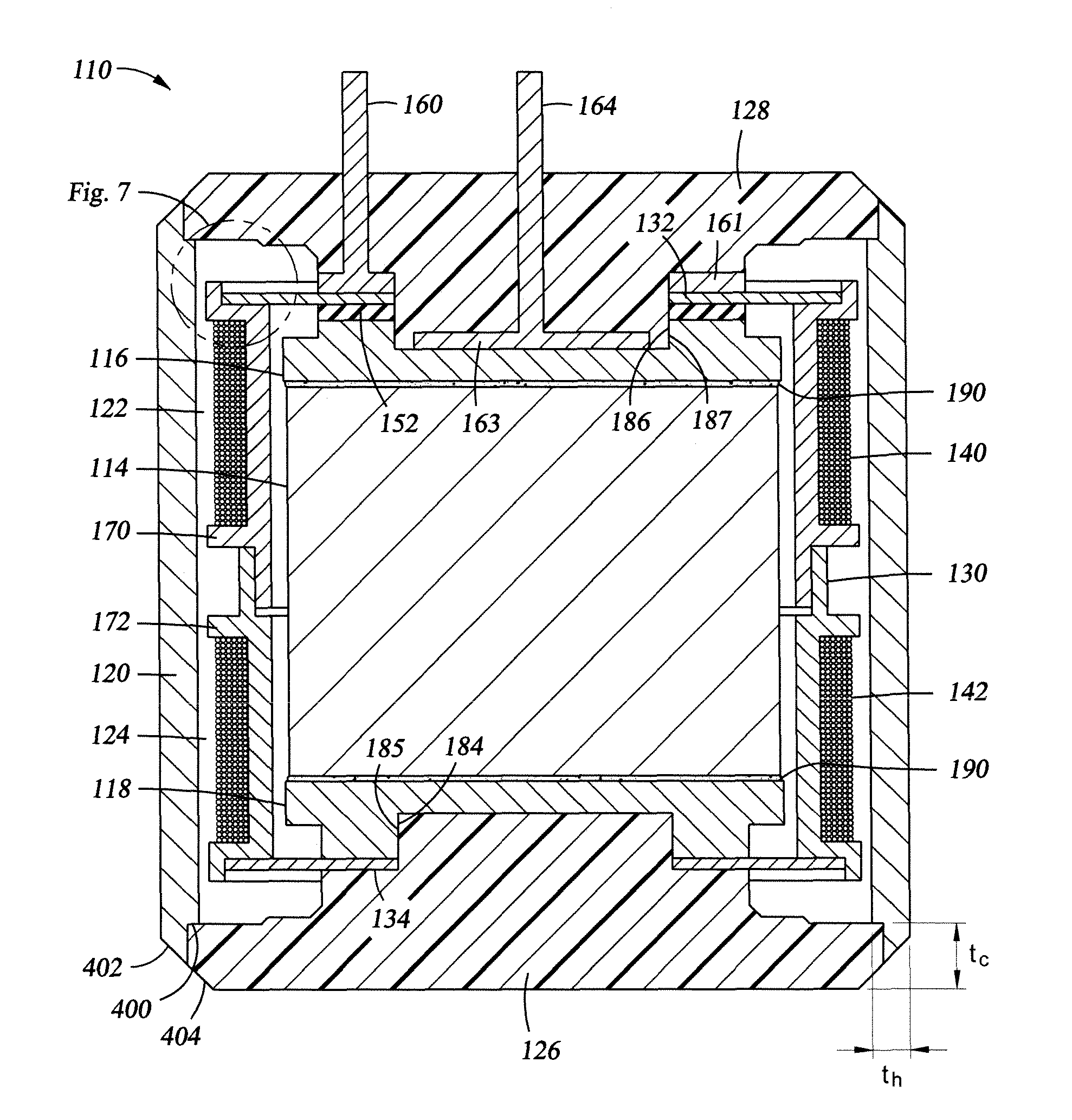
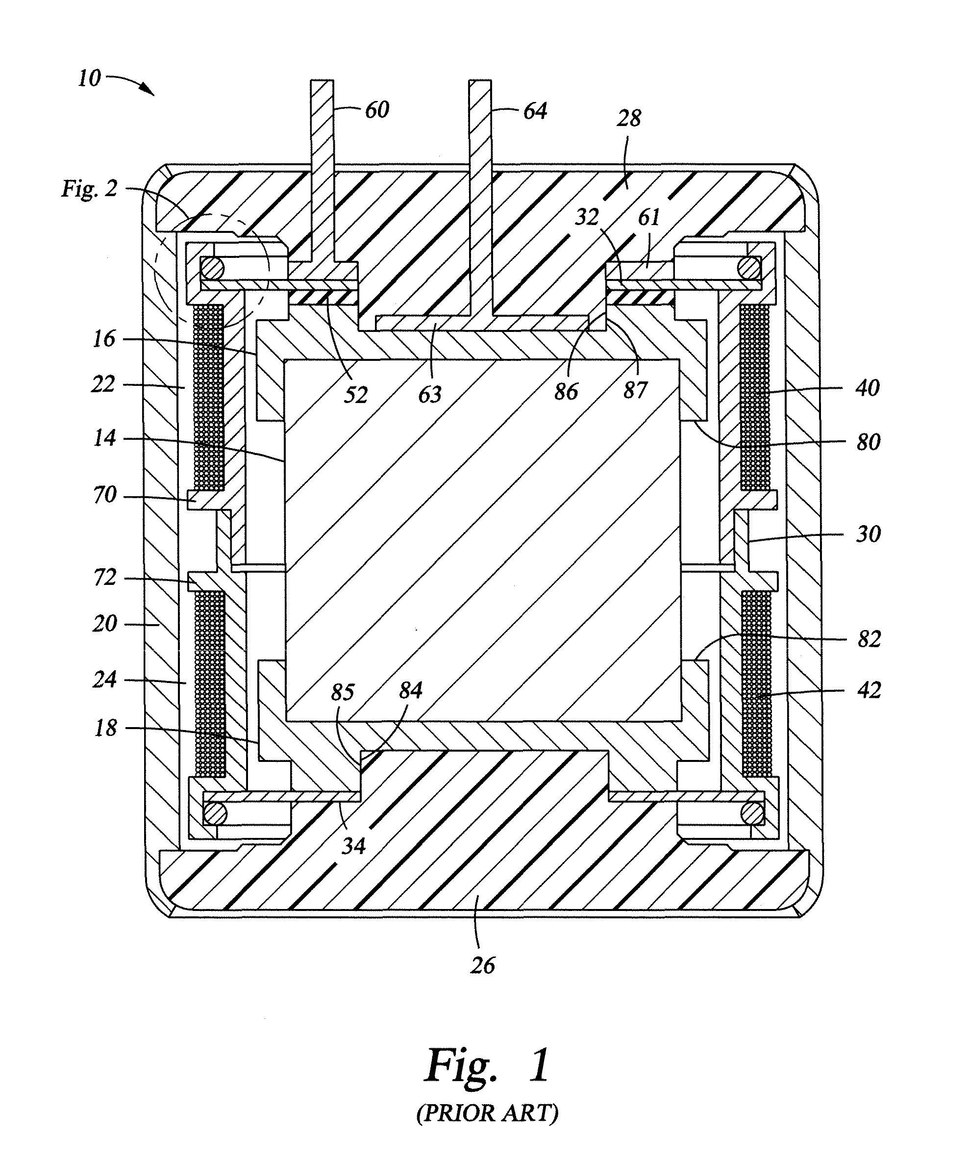
[0043]FIG. 4 illustrates an improved miniaturized geophone 110 according to the invention in a cross section taken along the longitudinal axis. Like prior art geophone 10 of FIG. 1, geophone 110 includes a cylindrical magnet 114, cylindrical upper and lower pole ferrous pole pieces 116, 118, and a tubular ferrous outer housing 120 that form a magnetic circuit including upper and lower annular air gaps 122, 124.

[0044]However, unlike the prior art pole pieces 16, 18, pole pieces 116, 118 are lipless. That is, each pole piece 116, 118 abuts an end of magnet 114 but does not extend out around the side of magnet 114. By eliminating pole piece lips that encircle the circumference of magnet 114, the diameters of coil form 130 and housing 120 can be reduced, thereby allowing a reduced geophone diameter for a given magnet diameter.

[0045]Because the pole pieces are lipless, in a preferred embodiment, pole pieces 116, 118 are fastened to magnet 114 with an adhesive to keep magnet 114 coaxially...

second embodiment

[0052]FIG. 5 illustrates an improved miniaturized geophone 210 according to the invention in a cross section taken along the longitudinal axis. Like geophone 110 of FIG. 3, geophone 210 includes lipless pole pieces 116, 118 that are bonded to magnet 114 with an epoxy or like thermosetting adhesive. However, rather than using an electrically conductive adhesive 190, an adhesive 290 with dielectric properties is used. If necessary, adhesive epoxy 290 may be made suitably electrically non-conductive by the addition of mica fillers such as borosilicate glass micro-spheres, for example. Other insulating fillers may also be used as appropriate.

[0053]The upper lead (not visible) of upper coil 140 is electrically connected to the outer circumference of upper frequency-tuned spring 132 by a solder joint, for example. The inner circumference of upper frequency-tuned spring 132 makes sliding electrical contact with an upper wiper ring assembly 261, which includes a lead 260 that passes through...


PUM


Abstract

A micro geophone having pole pieces do not extend out around the sides of the magnet, thereby allowing a reduced geophone diameter for a given magnet diameter. The pole pieces are adhesively bonded to the magnet using an adhesive, which may be made suitably electrically conductive by silver or nickel fillers or non-conductive by mica fillers such as borosilicate glass micro-spheres. Axial space is economized by eliminating traditional spider retaining rings. The spider springs are seated directly against the coil form and secured by adhesive fillets disposed on the outward-facing spring circumferences. The spider springs include circumferential notches to receive adhesive. A two-piece bimetallic coil form of aluminum and a heavier material, joined by adhesive, is provided. Headers are affixed to the housing within the seats by adhesive. A straight or rounded chamfer at each of the geophone ends allows the overall geophone dimensions to be maximized.

Description

BACKGROUND OF THE INVENTION[0001]1. Field of the Invention[0002]This invention relates generally to geophones used in seismic exploration.[0003]2. Description of the Prior Art[0004]FIG. 1 shows a vertical geophone (10) of conventional design. FIG. 1 is a cross section taken along the longitudinal axis of the geophone (10). The geophone (10) employs a cylindrical magnet (14), cylindrical upper and lower ferrous pole pieces (16, 18), and a tubular ferrous outer housing (20), which together form a magnetic circuit.[0005]The upper and lower pole pieces (16, 18) each have a cap-like shape so that they fit over and receive the upper and lower ends of the magnet (14), respectively. The tubular portion of the upper and lower pole pieces that enclose the sides of the cylindrical magnet (14) are referred to herein as pole piece lips (80, 82). The magnet (14) and pole pieces (16, 18) are received within the outer cylindrical housing (20). In addition to shaping magnetic flux across the air gap...

Claims


Application Information

Patent Timeline
Patent Type & Authority Patents(United States)
IPC IPC(8): H04R9/04G01V1/18
CPCG01V1/182
Inventor WOO, DANIEL, M.
Owner GEOSPACE TECH
Why Eureka
Try Eureka