Microfluidic chip for capillary electrophoresis separation and chemiluminescence detection

A technology of chemiluminescence detection and capillary electrophoresis, which is applied in the field of micro-total analysis system, can solve the problems that affect the stability of electrophoretic separation and the reproducibility of results, the chemiluminescence detection method has not been widely used, and the analysis speed is slow. Lightweight, improved detection sensitivity, and easy operation

Inactive Publication Date: 2010-04-07
ZHEJIANG UNIV
View PDF0 Cites 49 Cited by
  • Summary
  • Abstract
  • Description
  • Claims
  • Application Information

AI Technical Summary

Problems solved by technology

Therefore, the operation is complicated and the analysis speed is slow
[0006] In the existing microfluidic chips for capillary electrophoresis separation and chemiluminescence detection, the separation electric field of capillary electrophoresis passes through the detection channel or detection cell. When a photochemical reaction occurs in the detection channel or detection cell, the generated bubbles will affect the electrophoretic separation. The stability and reproducibility of the results, which are the common shortcomings of the above two methods
And the Y-type post-column reactor cannot be used in non-aqueous luminescent systems
[0007] For these reasons, chemiluminescent detection methods have not been widely used in microfluidic chip analysis systems

Method used


Image

  • Microfluidic chip for capillary electrophoresis separation and chemiluminescence detection
  • Microfluidic chip for capillary electrophoresis separation and chemiluminescence detection

Examples


Embodiment 1

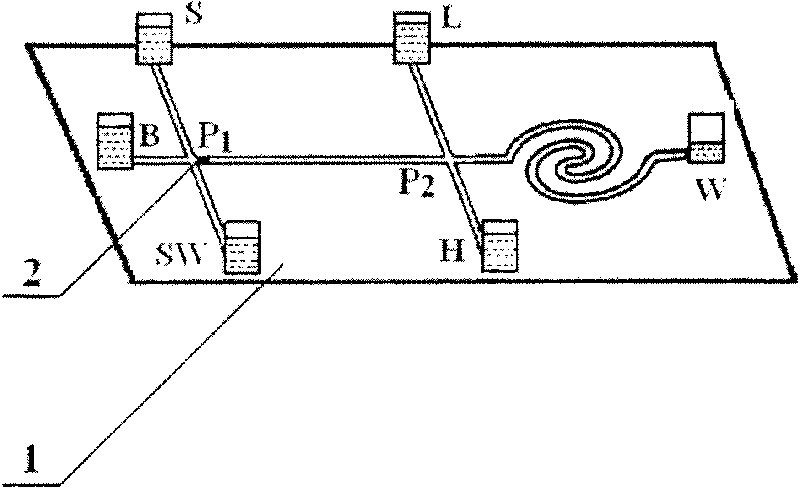
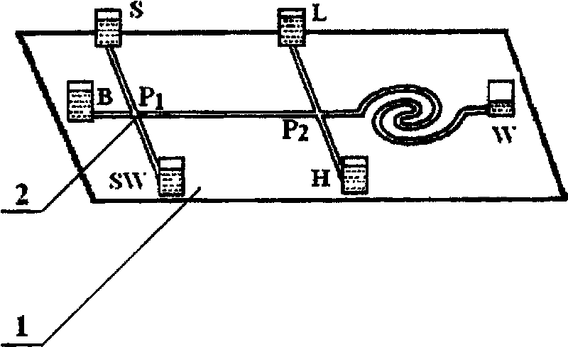
[0018] A microfluidic analysis chip integrating chip capillary electrophoresis separation and chemiluminescence detection. The chip is composed of a sample injection channel, a separation channel, a detection channel and a sheath flow channel. The sampling channel intersects with the separation channel, the terminal of the separation channel is connected with the starting point of the detection channel, and the sheath flow channel for passing the chemiluminescent reagent is also connected here as a branch pipe. The separation channel between the injection channel and the detection channel is an effective separation channel. Fabricate microporous plugs in active separation channels. The sample to be analyzed can enter the separation channel for electrophoretic separation driven by electroosmotic flow; while the luminescence reagent driven by pressure difference will not flow back into the separation channel.

[0019] see figure 1 , the microfluidic chip 1 has a buffer solutio...


PUM


Abstract

The invention discloses a microfluidic assay chip integrated capillary electrophoresis separation with chemiluminescence detection. The microfluidic chip consists of a buffer solution storage tank, a sample liquid storage tank, a sample waste liquid tank, a waste liquid tank, a sheath flow storage tank, a sample introduction channel, a separation channel, a sheath flow channel and a detection channel. A terminal of the separation channel and a starting point of the detection channel are communicated with the sheath flow channel. A chemiluminescence reagent enters the detection channel through the sheath flow channel; and when compositions to be assayed after the capillary electrophoresis separation of the chip meets the chemiluminescence reagent at a connecting point of the separation channel and the detection channel, the compositions are mixed with chemiluminescence reagent in the detection channel and then undergo luminous reaction. The inside of the separation channel is provided with a microporous plug to prevent the chemiluminescence reagent from flowing backwards into the separation channel under the driving of pressure difference so as not to influence electrophoresis separation. The microfluidic assay chip has the characteristics of high separation efficiency, high detection sensitivity, simple structure, small volume, light weight, convenient operation and the like, and is ideal to prepare a portable micro total separation system.

Description

technical field [0001] The invention relates to a micro-total analysis system, in particular to a microfluidic chip with integrated chip capillary electrophoresis separation and chemiluminescence detection and its use method. Background technique [0002] Since the concept of micro-total analysis system was proposed in 1990, microfluidic chip technology has opened up a broad space for development in the fields of chemistry, life science, environmental science and food science. Because chip capillary electrophoresis has the advantages of high separation efficiency, easy portability, less reagent consumption, and short analysis time, it is a commonly used separation technology in microchip analysis systems. However, the detection volume of chip capillary electrophoresis is small and the optical path is short, so the detector used with it must have extremely high sensitivity. [0003] Due to the high sensitivity of the laser-induced fluorescence detector and the low technical ...

Claims


Application Information

Patent Timeline
Patent Type & Authority Applications(China)
IPC IPC(8): G01N21/76B01D57/02
Inventor 殷学锋王修中
Owner ZHEJIANG UNIV
Why Eureka
Try Eureka