Planar illumination device

a technology of illumination device and illumination device, which is applied in the direction of instruments, optical light guides, optics, etc., can solve the problems of spoiled device appearan

Inactive Publication Date: 2017-10-05
MINEBEAMITSUMI INC
View PDF3 Cites 3 Cited by
  • Summary
  • Abstract
  • Description
  • Claims
  • Application Information

AI Technical Summary

Benefits of technology

[0005]In addition to a frame size reduction in the two sides perpendicular to the light-entering side of the light guide plate, a frame size reduction in the light-entering side is being requested. The inventors of the present invention therefore made a planar illumination device using a shielding member, the frame width of which was reduced, and found that an area of higher brightness (high brightness area) in a cross shape was problematically generated in the light-entering side, which spoiled the appearance of the device.

Problems solved by technology

The inventors of the present invention therefore made a planar illumination device using a shielding member, the frame width of which was reduced, and found that an area of higher brightness (high brightness area) in a cross shape was problematically generated in the light-entering side, which spoiled the appearance of the device.

Method used


Image

  • Planar illumination device
  • Planar illumination device
  • Planar illumination device

Examples


Embodiment Construction

[0017]An embodiment of a planar illumination device according to the present invention will now be described in detail with reference to the drawings. It should be noted that the embodiment is not intended to limit the scope of the invention. In the drawings, like numerals indicate like or corresponding components as appropriate.

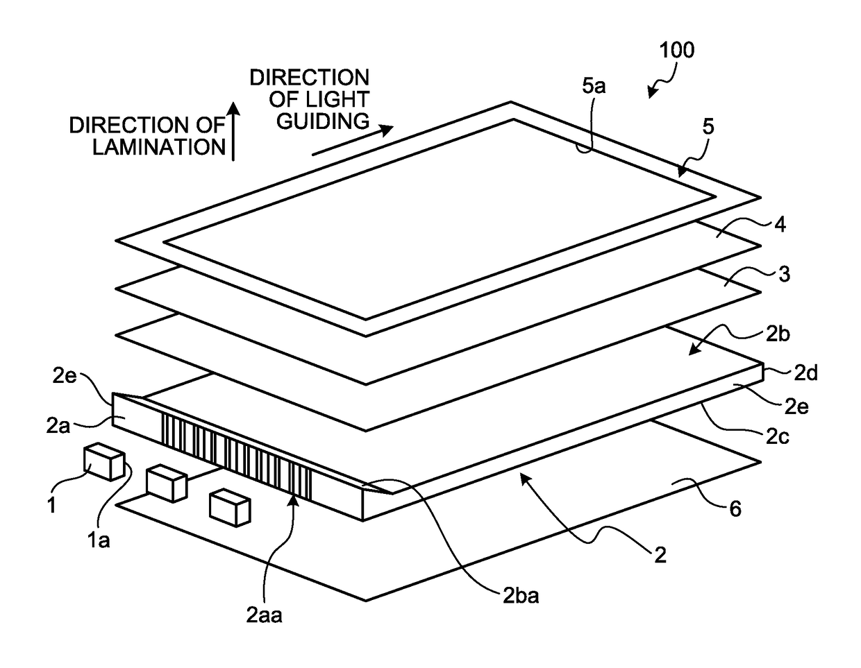
[0018]FIG. 1 is an exploded perspective view schematically illustrating the planar illumination device according to the embodiment. A planar illumination device 100 is in a rectangular shape in a top view and includes a plurality of light sources 1, a light guide plate 2, a light diffusion sheet 3, an optical sheet 4, a light-shielding member 5 serving as a fixing member, and a reflection sheet 6. These components configuring the planar illumination device 100 are accommodated in a frame (not illustrated), which is a frame-like member made of resin or the like, and / or supported by the frame. Each of the components is fixed to the frame with a double sided ta...


PUM


Abstract

A planar illumination device includes a light guide plate guiding a light entering from a light-entering end surface and emitting the light from a light-emission surface, and a fixing member disposed in a manner covering at least an area in the light-entering end surface side of the light-emission surface. The light guide plate has a plurality of first prisms formed on the light-emission surface in the area covered by the fixing member in the light-entering end surface side and a plurality of second prisms formed on the light-emission surface in an area covered by no fixing members. The number of second prisms per unit length in the width direction is smaller than the number of first prisms per unit length in the width direction. Each of the second prisms is formed successively to any of the first prisms in a top view.

Description

CROSS-REFERENCE TO RELATED APPLICATION(S)[0001]The present application claims priority to and incorporates by reference the entire contents of Japanese Patent Application No. 2016-075025 filed in Japan on Apr. 4, 2016.BACKGROUND OF THE INVENTION1. Field of the Invention[0002]The present invention relates to a planar illumination device.2. Description of the Related Art[0003]Planar illumination devices are used as a backlight of a liquid crystal display panel in a liquid crystal display device. Side-light planar illumination devices in which a light source including a light-emitting element such as a light emitting diode(LED) and a light guide plate are assembled are widely used for small mobile information apparatuses such as a mobile phone (see Japanese Patent Application Laid-open No. 2004-354727, for example).[0004]Such a planar illumination device includes a frame-like light-shielding member for defining an effective area for light emission. For a size reduction and sophisticati...

Claims


Application Information

Patent Timeline
Patent Type & Authority Applications(United States)
IPC IPC(8): F21V8/00
CPCG02B6/0036G02B6/0055G02B6/0088G02B6/0051G02B6/0053G02B6/0016G02B6/002G02B6/0058G02F1/133606G02F1/133607G02B6/0018G02B6/0038G02B6/0065
Inventor YOSHIDA, TAKAHITO
Owner MINEBEAMITSUMI INC
Why Eureka
Try Eureka