Press formed component and method for manufacturing same

a technology of components and components, applied in metal-working feeding devices, manufacturing tools, transportation and packaging, etc., can solve problems such as wrinkles on the vertical wall

Pending Publication Date: 2021-12-09
JFE STEEL CORP
View PDF0 Cites 0 Cited by
  • Summary
  • Abstract
  • Description
  • Claims
  • Application Information

AI Technical Summary

Benefits of technology

[0011]Performing press forming under the condition described in PTL 1 can suppress cracking in the flange portion and wrinkling on the top sheet portion in the portion curved inward in a plan view (also referred to as curved inner side) in the L-shape. However, in the method described in PTL 1, wrinkles occur on the vertical wall portion on the curved inner side depending on the shape of the press formed component. The occurrence of wrinkles spoils the appearance of a product or can cause a defect during welding with another component at the position of the vertical wall portion.
[0013]Aspects of the present invention have been made in view of the above problems, and it is an object according to aspects of the present invention to provide a press formed component capable of suppressing wrinkling on a vertical wall portion of a curved portion in a component shape having an L-shape, a T-shape, or the like when viewed in a plan view and a method for manufacturing the same.
[0018]According to the aspects of the present invention, by simply specifying the shape condition of the press formed component shape, there can be provided a press formed component capable of suppressing the occurrence of wrinkles on the vertical wall portion of the curved portion in the component shape having an L-shape, a T-shape, or the like when viewed in the plan view.

Problems solved by technology

However, in the method described in PTL 1, wrinkles occur on the vertical wall portion on the curved inner side depending on the shape of the press formed component.
The occurrence of wrinkles spoils the appearance of a product or can cause a defect during welding with another component at the position of the vertical wall portion.

Method used


Image

  • Press formed component and method for manufacturing same
  • Press formed component and method for manufacturing same
  • Press formed component and method for manufacturing same

Examples


example

[0081]An Example based on the present embodiment will be described.

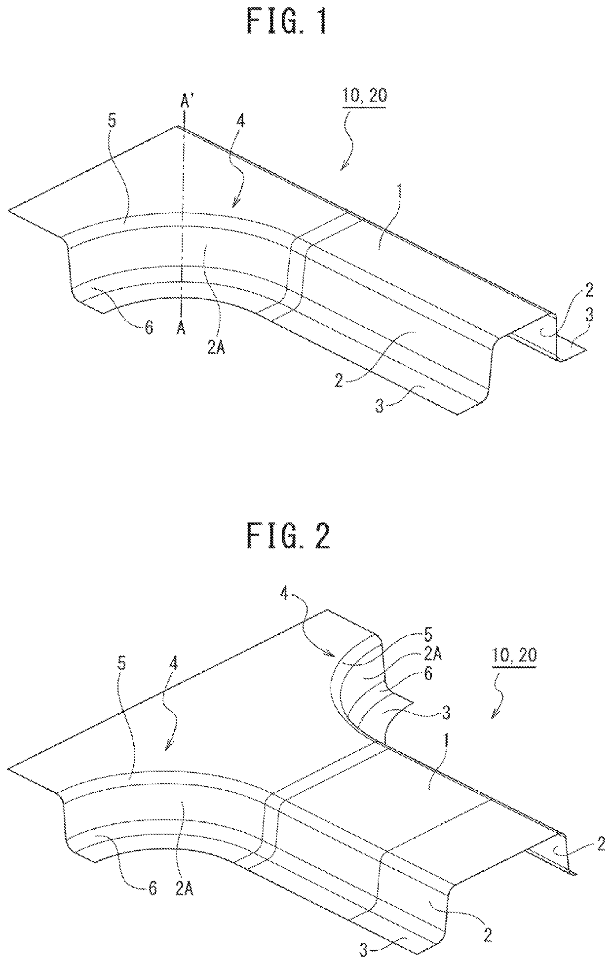
[0082]A 980 MPa-class cold-rolled steel sheet (sheet thickness: 1.4 mm) was used as the material metal sheet, and a component shape having a T-shape as illustrated in FIG. 12 was set as the curve-containing component shape 10. The component shape includes the curved portion 4 on each widthwise side of the top sheet portion 1 on the left side on the paper in FIG. 12.

[0083]The following conditions were adopted as forming analysis conditions for the geometric shape of the above component.

[0084]

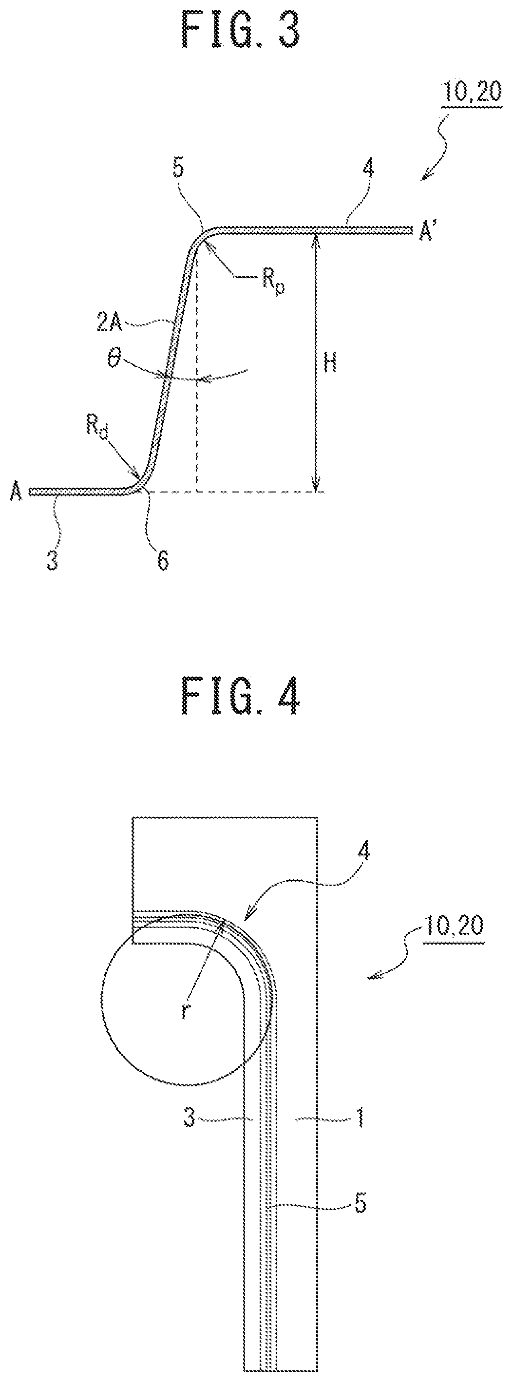
[0085]Height H of vertical wall portion: 60 mm

[0086]Inclination angle θ: 2 deg, 7 deg, and 12 deg

[0087]Length f at an outer edge of the flange portion 3 in the curved portion 4: 30 mm

[0088]Punch shoulder R (curvature radius Rp at boundary portion 5): 10 mm

[0089]Die shoulder R (curvature radius Rd at boundary portion 6): 8 mm, 12 mm, and 16 mm

[0090]Curved portion R (curvature radius r of curved portion): 100 mm, 150 mm, and 200 mm

[...


PUM

PropertyMeasurementUnit
tensile strengthaaaaaaaaaa
inclination angleaaaaaaaaaa
heightaaaaaaaaaa

Abstract

Provided are a press formed component that does not easily cause wrinkling on a vertical wall portion of a curved portion in a component shape having an L-shape, a T-shape, or the like when viewed in a plan view and a method for manufacturing the same. A press formed component includes a top sheet portion, a vertical wall portion continuous to the top sheet portion, and a flange portion and also includes a curved portion in which when viewed in a plan view, at least a part of a boundary portion between the top sheet portion and the vertical wall portion is displaced to the vertical wall portion side and curved concavely toward a longitudinal direction. In a cross-sectional shape of the curved portion, an inclination angle θ [deg] of the vertical wall portion with respect to the top sheet portion satisfies the following expression: (1−sin θ) / cos θ>0.95.

Description

CROSS REFERENCE TO RELATED APPLICATIONS[0001]This is the U.S. National Phase application of PCT / JP2019 / 025968, filed Jun. 28, 2019, which claims priority to Japanese Patent Application No. 2018-205495, filed Oct. 31, 2018, the disclosures of these applications being incorporated herein by reference in their entireties for all purposes.FIELD OF THE INVENTION[0002]The present invention relates to a press formed component including a portion having an L-shape, a T-shape, or the like in a plan view, which is used as, for example, a skeleton component of an automobile, and to a method for manufacturing the same. Here, the component L-shaped or T-shaped in a plan view includes a curved portion in which a boundary portion between a top sheet portion and a vertical wall portion is displaced to the vertical wall portion side and curved concavely toward a longitudinal direction.BACKGROUND OF THE INVENTION[0003]A front pillar, a center pillar, or the like, which is a vehicle body skeleton comp...

Claims


Application Information

Patent Timeline
Patent Type & Authority Applications(United States)
IPC IPC(8): B21D5/06B21D22/22B21D22/26B21D43/05B21D53/88
CPCB21D5/06B21D22/22B21D53/88B21D43/05B21D22/26B21D22/20
Inventor MIYAKE, HIROTOSHINMIYA, TOYOHISAYAMASAKI, YUJI
Owner JFE STEEL CORP
Why Eureka
Try Eureka