Light splitting module for obtaining spectrums and dual-mode multiplexing optical device
a spectrum and light splitting technology, applied in the field of optical imaging, can solve the problems of bulky and costly, conventional spectrometers rely on a large number of optical components, and achieve the effects of low cost, high resolution, and simple manufacturing process
- Summary
- Abstract
- Description
- Claims
- Application Information
AI Technical Summary
Benefits of technology
Problems solved by technology
Method used
Image

Examples
first preferred embodiment
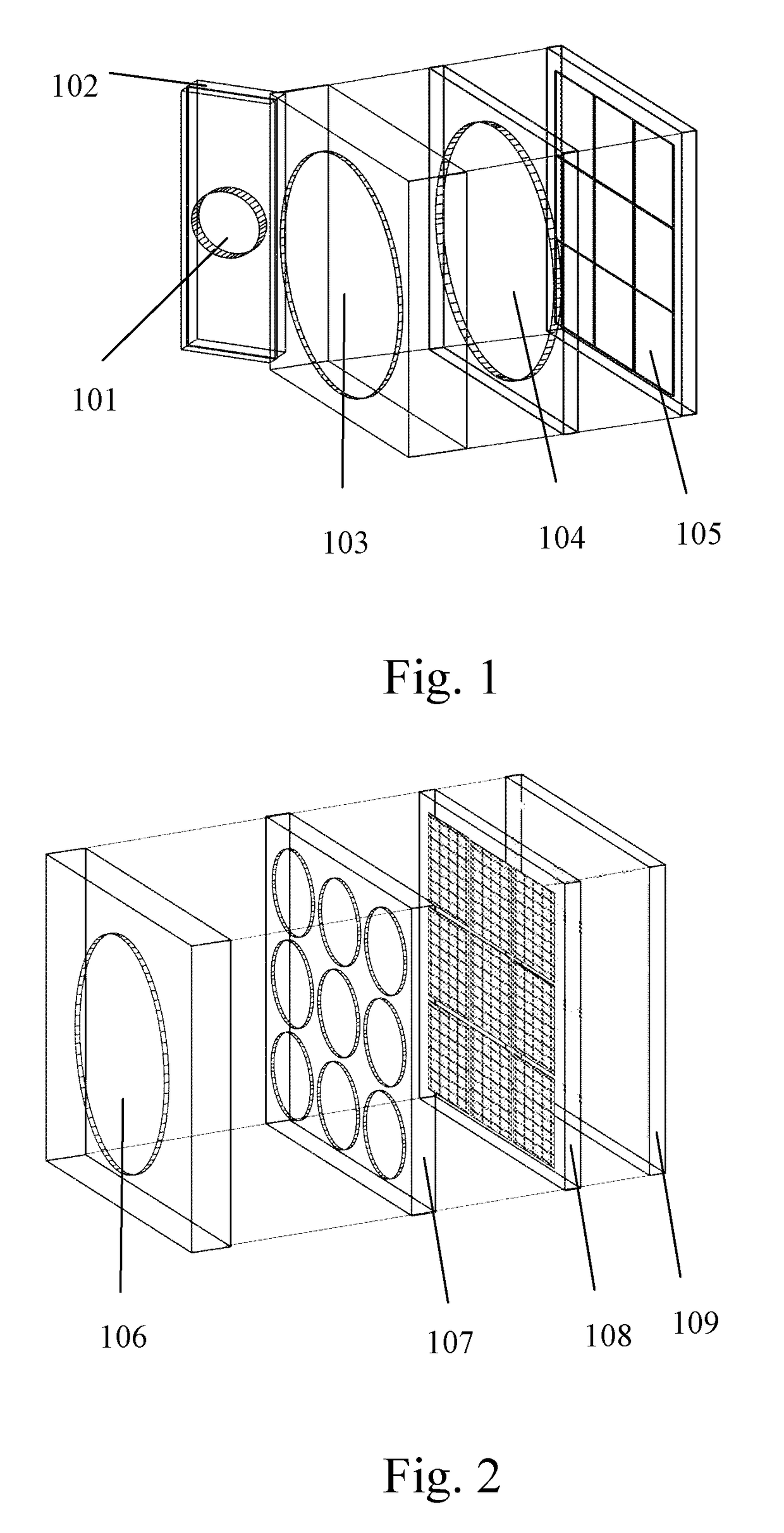
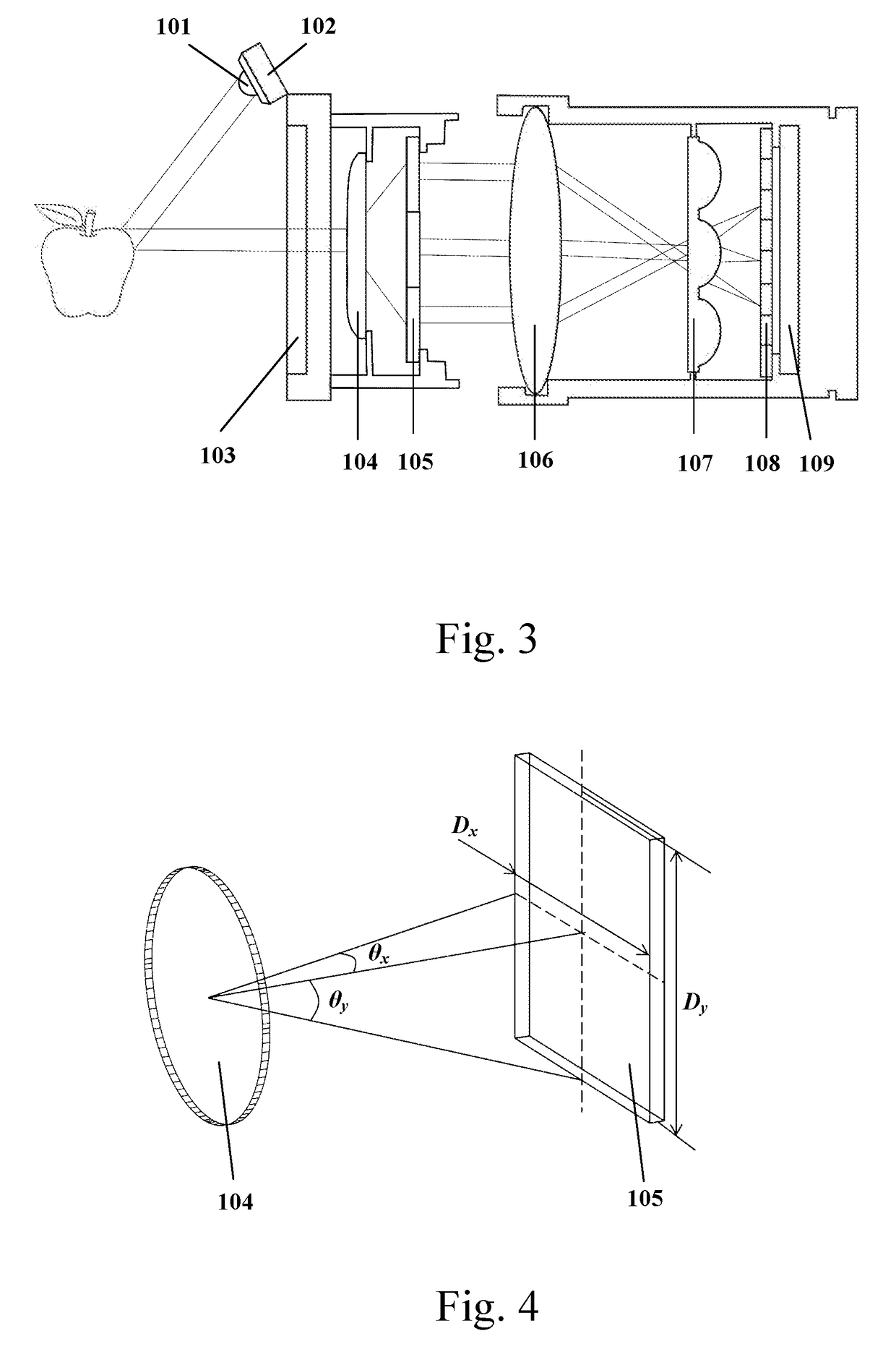
[0032]As shown in FIG. 1, a light splitting module for obtaining spectrums of an object to be tested is illustrated, which sequentially comprises a light entrance window 103, a diffuser 104 and a filter array 105 along a light entrance direction, wherein a size of the filter array is Dx×Dy. Referring to FIG. 4, maximum divergent angles of the diffuser along a horizontal direction and a vertical direction thereof are respectively θx and θy; a distance d between the filter array and the diffuser meets
0d≤min{Dx2cotθx,Dy2cotθy};
when the above-mentioned conditions are met, the device space is able to be effectively utilized; when are not, a partial area of the filter array is wasted. The light entrance window is made from materials which are transparent at specific bands, and the specific bands are target bands of the light splitting module. The filter array is an angle modulated filter array and has a series of subareas, and a filter is provided on every subarea, that is, the filter arr...
second preferred embodiment
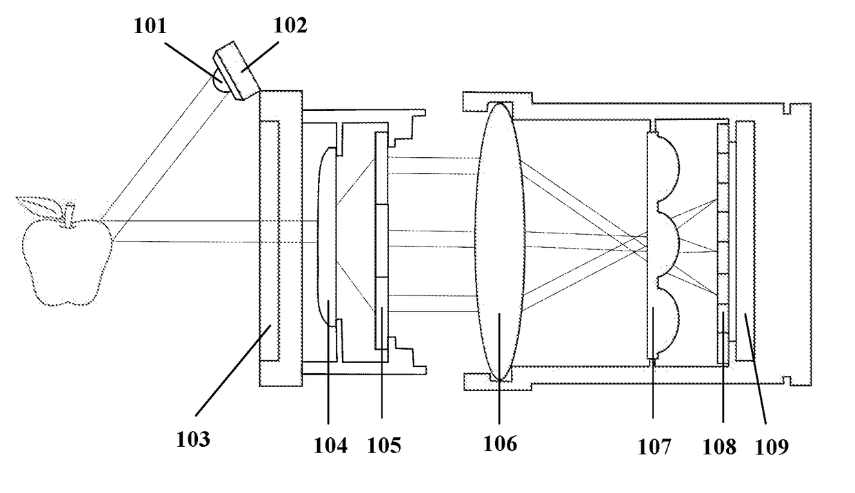
[0033]As shown in FIG. 3, a dual-mode multiplexing optical device comprises the light splitting module described according to the first preferred embodiment of the present invention. The dual-mode multiplexing optical device further comprises an illumination module adapted for providing an object to be tested with illumination, which comprises a light source 101; a light field imaging module, adapted for achieving light field imaging of the object to be tested, sequentially comprises a convergent lens 106, a microlens array 107, a detector 108 and a first control circuit 109 along a light entrance direction, wherein: the convergent lens converges lights from the filter array on a plane of microlenses of the microlens array, the microlens array projects lights from the filters corresponding to the microlenses on the detector in a form of spectrums, the detector detects the spectrums or light field imaging results of the object to be tested, the first control circuit controls the dete...
third preferred embodiment
[0047]As shown in FIG. 2, the light field imaging module is adopted to achieve the light field camera function in this embodiment.
[0048]The light field imaging module, adapted for achieving light field imaging of the object to be tested, sequentially comprises a convergent lens 106, a microlens array 107, a detector 108 and a first control circuit 109 along a light entrance direction, wherein: the convergent lens converges lights from the filter array on a plane of microlenses of the microlens array, the microlens array projects lights from the filters corresponding to the microlenses on the detector in a form of spectrums, the detector detects the spectrums or light field imaging results of the object to be tested, the first control circuit controls the detector to shoot the spectrums and the light field imaging results.
[0049]The detector is able to be any one of existing detectors, such as CCD or CMOS.
[0050]The microlenses of the microlens array are respectively corresponding to t...
PUM
 Abstract
Description
Claims
Application Information
 - R&D Engineer
- R&D Manager
- IP Professional
- Industry Leading Data Capabilities
- Powerful AI technology
- Patent DNA Extraction
Browse by: Latest US Patents, China's latest patents, Technical Efficacy Thesaurus, Application Domain, Technology Topic.
© 2024 PatSnap. All rights reserved.Legal|Privacy policy|Modern Slavery Act Transparency Statement|Sitemap