

Test device and test method
a test device and test method technology, applied in the direction of electrical equipment, etc., can solve the problems of unreliable test of operation or position of each microphon
- Summary
- Abstract
- Description
- Claims
- Application Information
AI Technical Summary
Benefits of technology
Problems solved by technology
Method used
Image

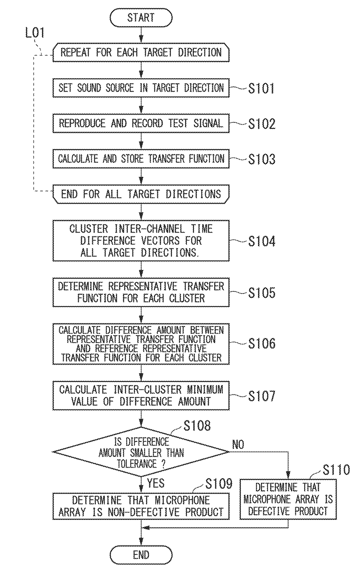
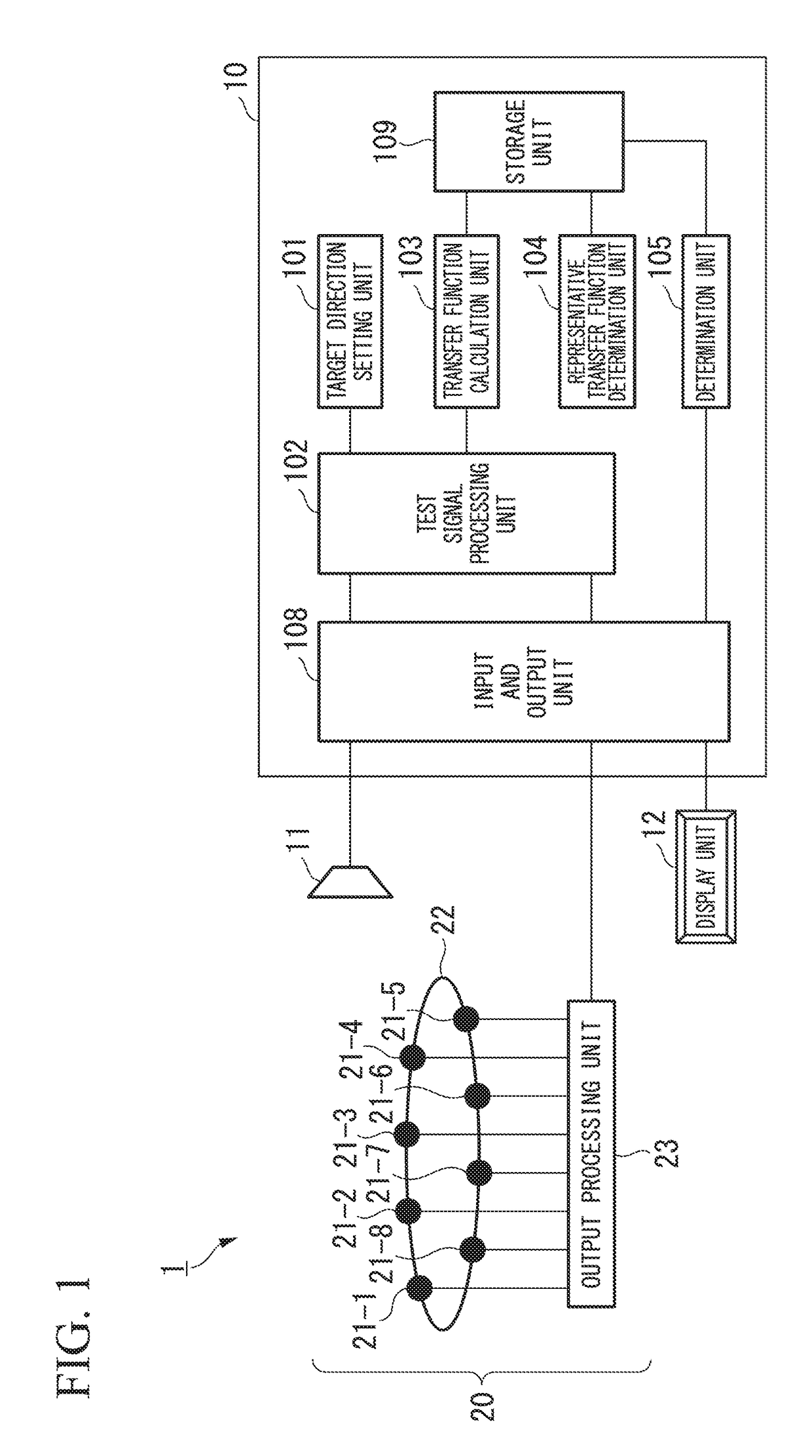
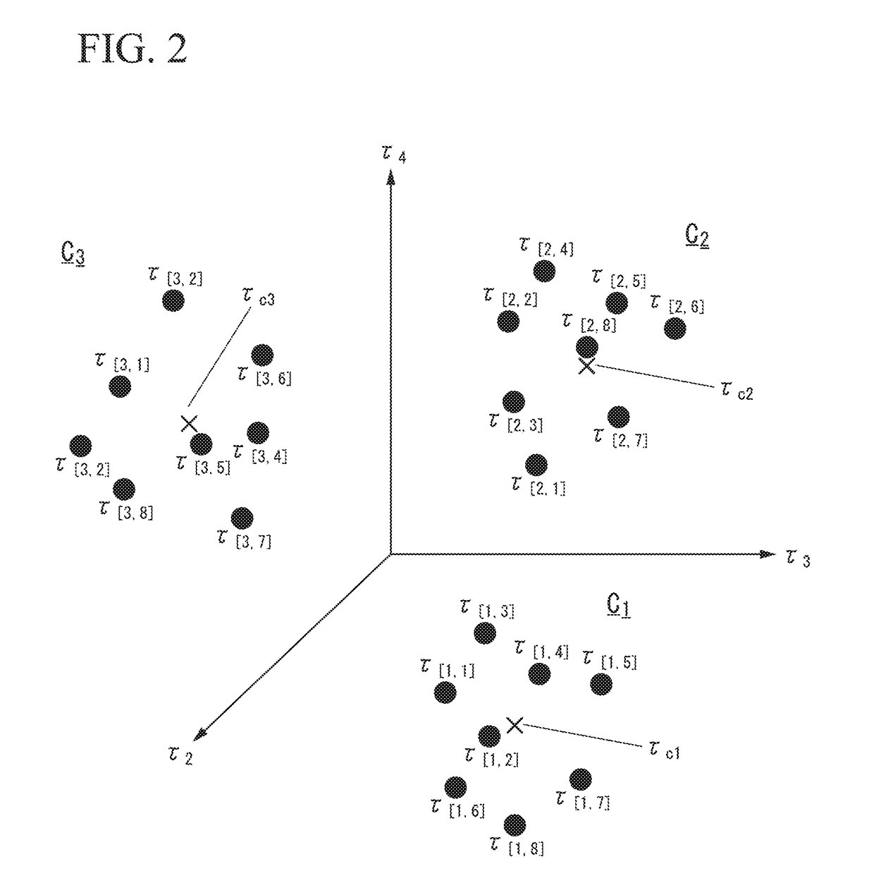
Examples
modification example
[0104]Next, a modification example according to the embodiment will be described.
[0105]FIG. 5 is a block diagram illustrating a configuration of a test system 1 according to this modification example.
[0106]In the test system 1 according to this modification example, a test device 10 further includes a calibration value calculation unit 106.
[0107]The calibration value calculation unit 106 calculates a calibration value for reducing the difference amount C with the reference representative transfer function Hm′(d, f) of the cluster d corresponding to the target direction θ when the transfer function H[n]m(θ, f) obtained from the reception signal of each channel m is multiplied by the calibration value. For example, the calibration value calculation unit 106 calculates an inter-cluster average of a ratio of the reference representative transfer function Hm′(d, f) to the representative transfer function Hm(d, f) as the calibration value Fm(f), as shown in Equation (10). In Equation (10)...
PUM
 Abstract
Description
Claims
Application Information