CATV uplink optical transmission system

a transmission system and optical transmission technology, applied in the field of uplink optical transmission system, can solve the problems of demodulating section receiving an aggregate of noise, degrading the noise characteristics of the optical transmission system, and affecting the effect of nois

Inactive Publication Date: 2005-11-24
PANASONIC CORP
View PDF12 Cites 8 Cited by
  • Summary
  • Abstract
  • Description
  • Claims
  • Application Information

AI Technical Summary

Benefits of technology

[0012] Therefore, an object of the present invention is to provide a CATV uplink optical transmission system configured so as to prevent an influence of noise occurring in one optical transmission system due to the absence of an uplink signal, the influence being exerted upon communications performed by other optical transmission systems.

Problems solved by technology

However, the conventional CATV uplink optical transmission system has some drawbacks.
Therefore, the demodulating section may receive an aggregate of noise, for example, occurring at the subscriber networks.
Such noise are called ingress noise, causing a problem in configuring the CATV uplink optical transmission system.
Such a non-linear phenomenon greatly degrades noise characteristics of the optical transmission system.
For this reason, noise occurring in one optical transmission system can considerably affect communications in other optical transmission systems.

Method used


Image

  • CATV uplink optical transmission system
  • CATV uplink optical transmission system
  • CATV uplink optical transmission system

Examples


first embodiment

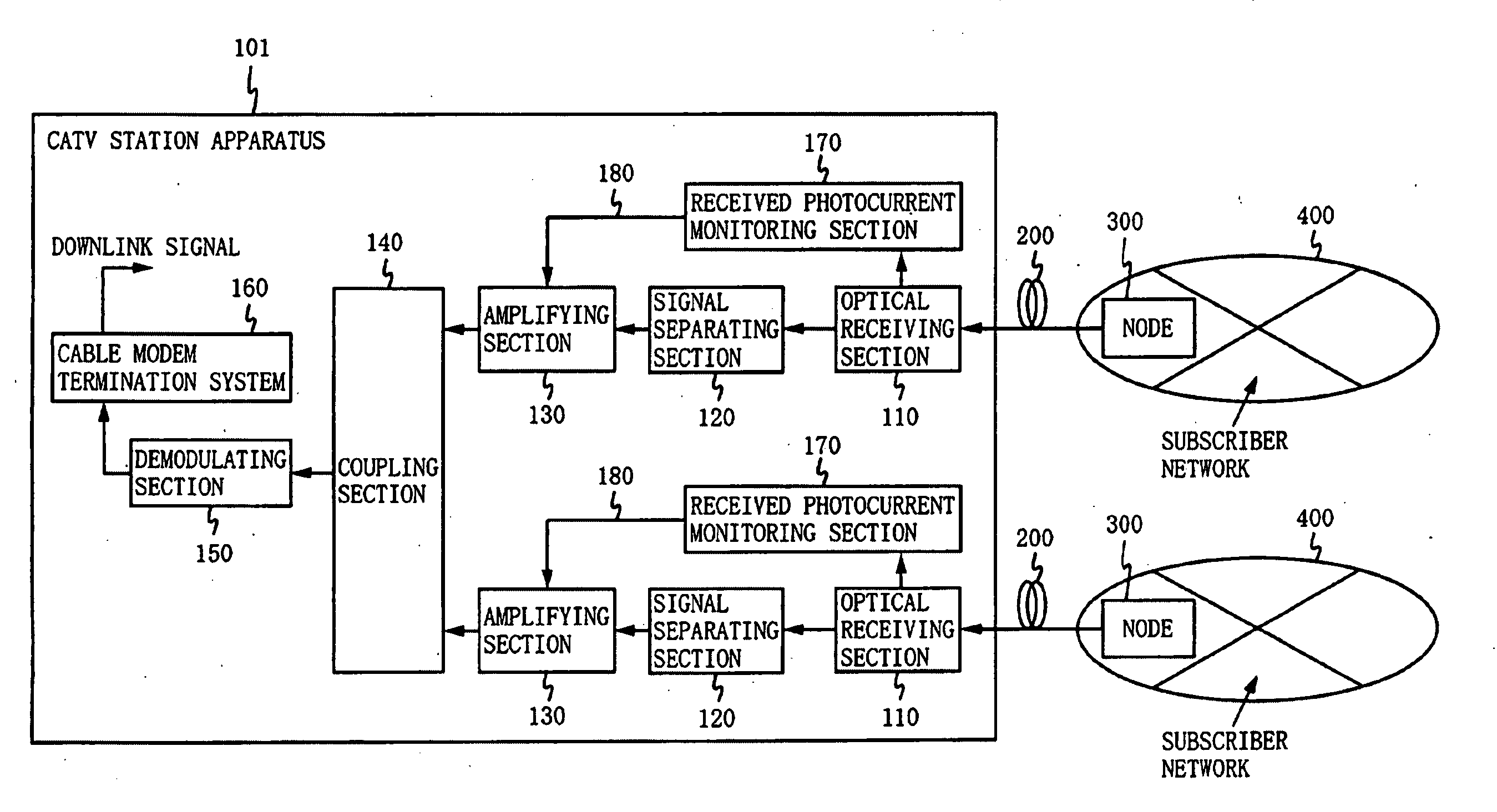
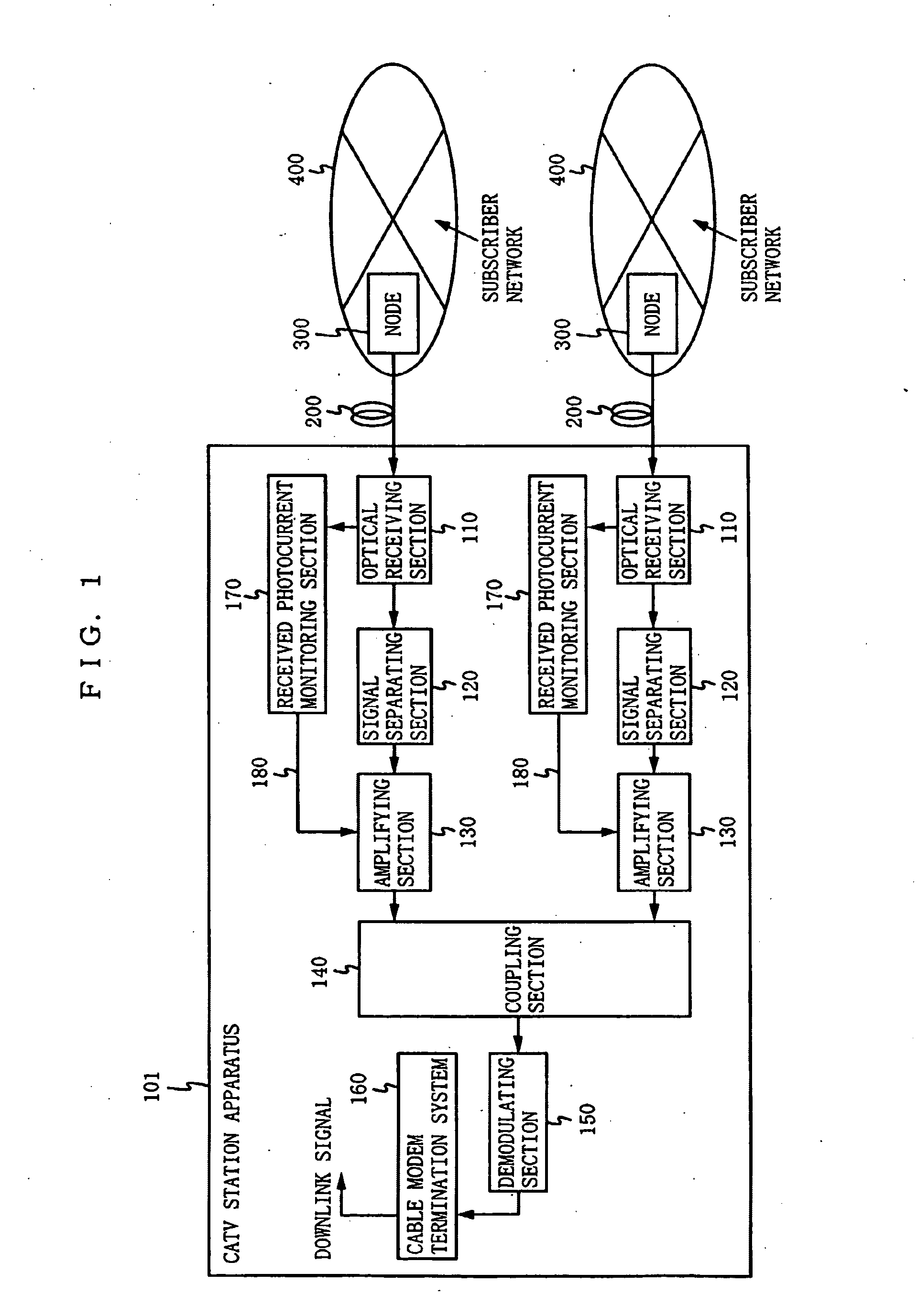
[0048]FIG. 1 is an illustration showing the configuration of a CATV uplink optical transmission system according to a first embodiment of the present invention. The system illustrated in FIG. 1 includes a CATV station apparatus 101, a plurality of optical fibers 200, a plurality of nodes 300, and a plurality of subscriber networks 400. Each of the subscriber networks 400 is a coaxial network for signal transmission using a coaxial transmission line, and is connected via the corresponding node 300 and the corresponding optical fiber 200 to the CATV station apparatus 101.

[0049] Each of the nodes 300 converts a signal transmitted from a subscriber device (not shown) connected to the corresponding subscriber network 400 to an optical signal, and then transmits the optical signal via the optical fiber 200 to the CATV station apparatus 101. The node 300 according to the present embodiment is the same as the node included in the above-described conventional CATV uplink optical transmissio...

second embodiment

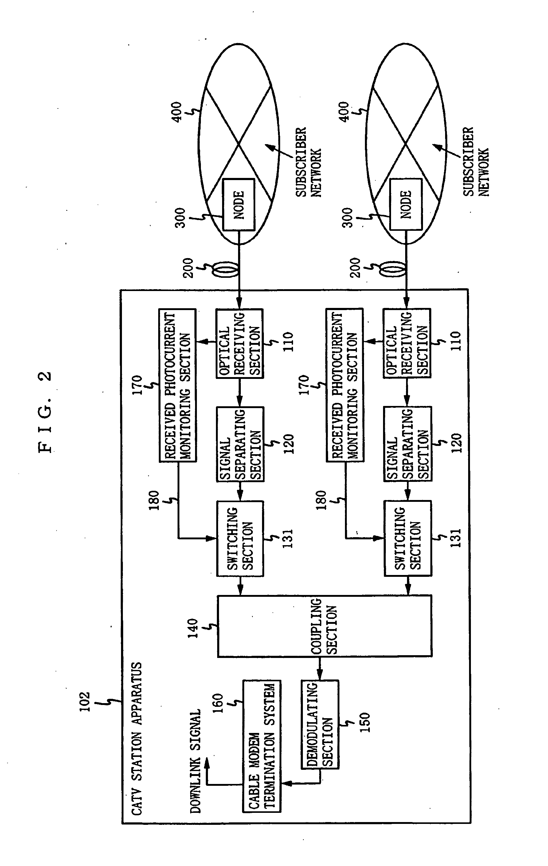
[0058]FIG. 2 is an illustration showing the configuration of a CATV uplink optical transmission system according to a second embodiment of the present invention. The system illustrated in FIG. 2 includes a CATV station apparatus 102, a plurality of optical fibers 200, a plurality of nodes 300, and a plurality of subscriber networks (coaxial networks) 400. In the present embodiment, components that are the same as those in the first embodiment are provided with the same reference numerals, and are not described herein.

[0059] The CATV station apparatus 102 is similar in function to the CATV station apparatus 101 according to the first embodiment, except that the amplifying sections 130 are replaced by switching sections 131.

[0060] Each of the switching sections 131 switches a transmission path for the data communication signal output from the corresponding signal separating section 120 in accordance with the control signal 180 output from the corresponding received photocurrent moni...

third embodiment

[0065]FIG. 3 is an illustration showing the configuration of a CATV uplink optical transmission system according to a third embodiment of the present invention. The system illustrated in FIG. 3 includes a CATV station apparatus 103, a plurality of optical fibers 200, a plurality of nodes 300, and a plurality of subscriber networks (coaxial networks) 400. In the present embodiment, components that are the same as those in the first embodiment are provided with the same reference numerals, and are not described herein.

[0066] The CATV station apparatus 103 is similar in function to the CATV station apparatus 101 according to the first embodiment, except that the received photocurrent monitoring sections 170 are replaced by uplink signal detecting sections 171.

[0067] Each of the uplink signal detecting sections 171 detects the presence or absence of an uplink signal included in the electrical signal output from the optical receiving section 110, and then outputs a control signal 181 i...


PUM


Abstract

A CATV station apparatus 100 subjects received optical signals to processes of optical-electrical conversion, signal separation, coupling, and demodulation for obtaining an uplink signal. A received photocurrent monitoring section 170 compares a received photocurrent at a optical receiving section 110 with a predetermined reference current. If the received photocurrent is equal to or higher than the reference current, an amplifying section 130 amplifies a signal output from a signal separating section 120 at a predetermined level. If the received photocurrent is lower than the reference current, on the other hand, it is determined that a non-linear phenomenon, such as stimulated Brillouin scattering, has occurred in an optical fiber 200. The amplifying section 130 then outputs a signal at a level which does not affect, even after being coupled with other signals, communications performed by other optical transmission systems.

Description

BACKGROUND OF THE INVENTION [0001] 1. Field of the Invention [0002] The present invention relates to an uplink optical transmission system included in a CATV system for performing bi-directional communications by using a bi-directional transmission line which is formed by connecting an optical fiber and a coaxial transmission line. [0003] 2. Description of the Background Art [0004] Conventionally, it has been known that a network of a CATV (Cable Television) system can be constructed by using a bi-directional transmission line called an HFC (Hybrid Fiber Coax) which is formed by connecting an optical fiber and a coaxial transmission line. The HFC is disclosed in, for example, Japanese Patent Laid-Open Publication No. 11-284999 (1999-284999). For the purpose of achieving bi-directional communications between a CATV station and a plurality of subscriber devices, the CATV system using an HFC has a network structure in which each subscriber device belongs to any one of subscriber networ...

Claims


Application Information

Patent Timeline
Patent Type & Authority Applications(United States)
IPC IPC(8): H04B10/2537H04B10/27H04B10/272
CPCH04B10/2537H04B10/272H04B10/27
Inventor MASUDA, KOUICHISASAI, HIROYUKIKIDO, SHINICHISOGABE, HIDEYUKI
Owner PANASONIC CORP
Why Eureka
Try Eureka