
Device for adjusting colour video signals

a technology for adjusting devices and colour video signals, applied in the direction of color television, image data processing details, image data processing, etc., can solve the problems of colour errors, conspicuous colour corruption, and remaining,

Inactive Publication Date: 2006-04-06
GRASS VALLEY CANADA
View PDF13 Cites 8 Cited by
  • Summary
  • Abstract
  • Description
  • Claims
  • Application Information

AI Technical Summary

Benefits of technology

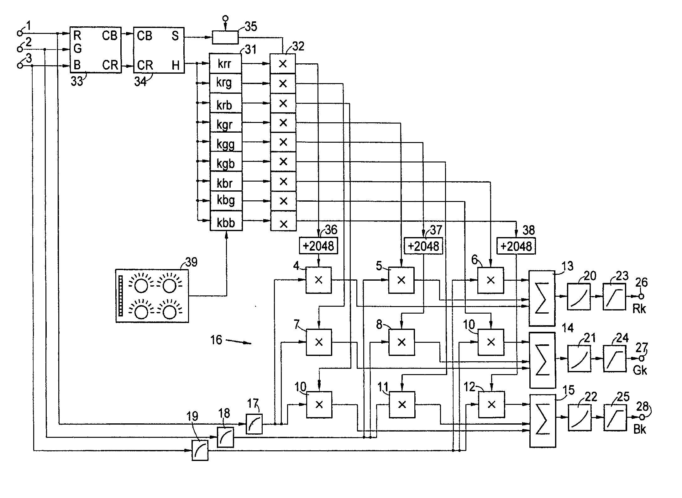
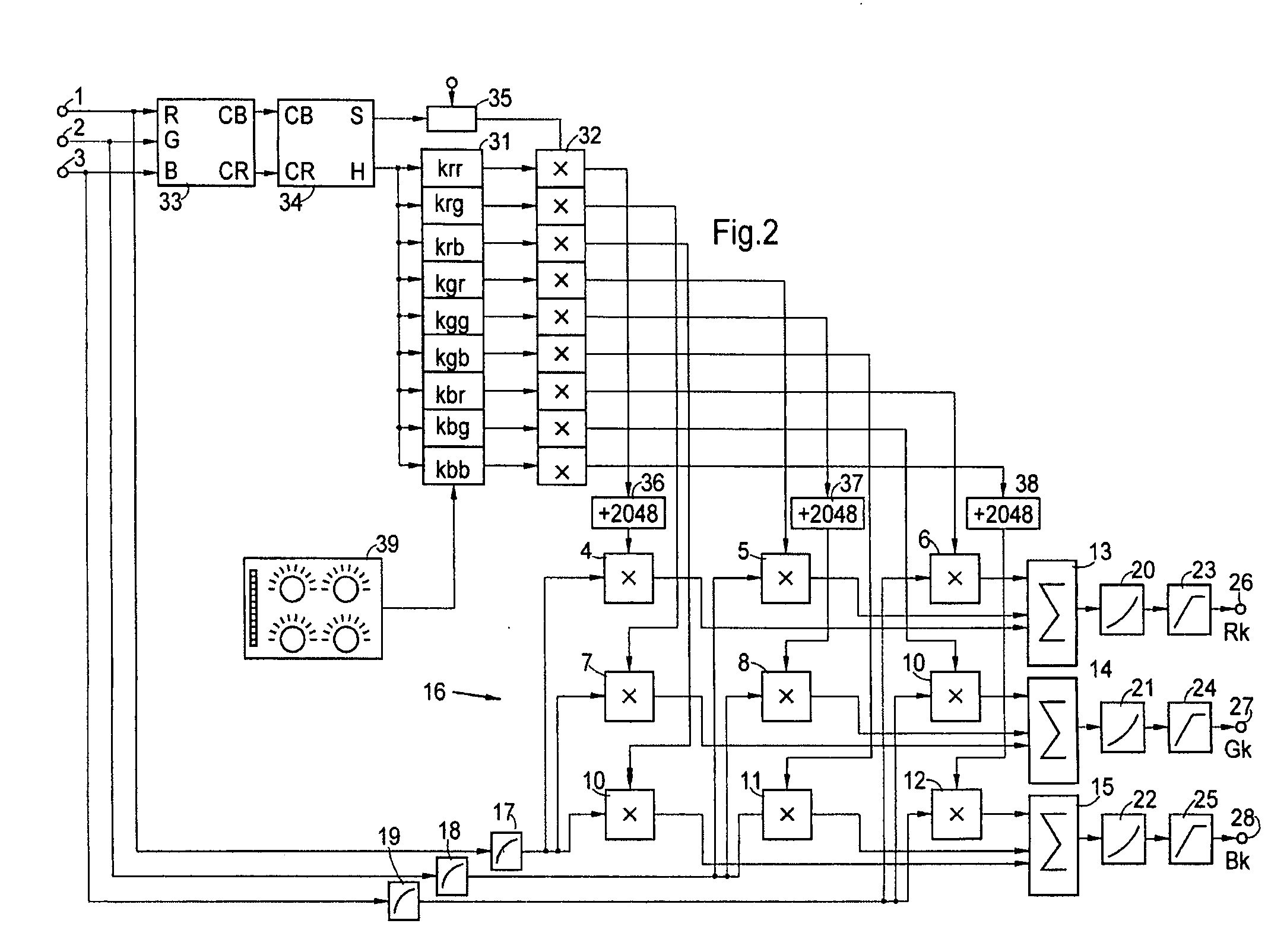
[0004] The arrangement according to the invention is characterized in that provision is made of means for controlling the matrix in a manner dependent on the hue which the colour video signals respectively represent. The arrangement according to the invention enables such a precise correction of the colour video signals that the same film produces an identical colour impression when scanned by different apparatuses.
[0006] In order to avoid noise influences and exaggerated corrections of pixels with low colour saturation, in one development of the invention, provision is made of means for reducing the effect of the correction in the case of low colour saturation.
[0010] For setting the corrections, it is preferably provided that the correction values can be loaded into the memories from a computer, and in that the computer has a program for setting the coefficients. The computer may be provided with corresponding input devices, for example rotary regulators, which facilitate a selection of the hue that is respectively to be corrected and the setting of the magnitude and direction of the correction.

Problems solved by technology

When generating colour video signals from optical originals, for example when scanning films, colour errors occur, inter alia, by virtue of the fact that the filter curves during colour splitting do not correspond to the ideal curves.
The remaining, generally slight colour corruptions are conspicuous, however, particularly when the same original is scanned by two different recording apparatuses, particularly when the same film is reproduced by two different film scanners.

Method used


Image

  • Device for adjusting colour video signals
  • Device for adjusting colour video signals
  • Device for adjusting colour video signals

Examples


Embodiment Construction

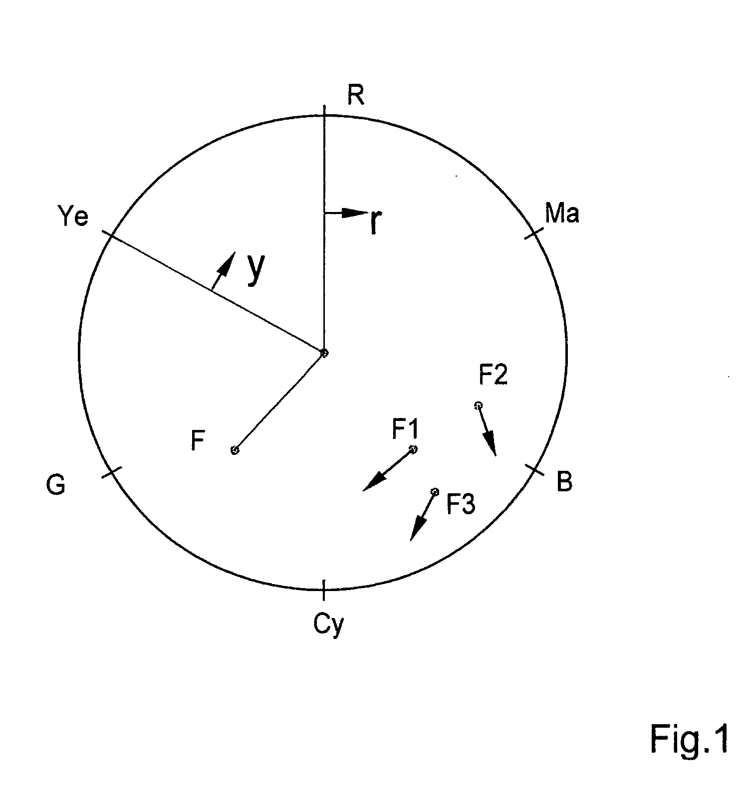
[0017] In the case of the representation of colours that is known per se in accordance with FIG. 1, each colour F can be represented by a vector whose magnitude corresponds to the colour saturation and whose angle corresponds to the hue. The chromatic circle contains all colours that can be represented, in particular the primary colours R, G, B and the intermediate colours Ye, Ma and Cy (yellow, magenta, cyan). The arrangement according to the invention can set and carry out a correction for each hue, which is represented for example by two arrows r and y in FIG. 1. This correction can be carried out with the aid of the arrangement illustrated in FIG. 2. If the colour saturation is furthermore taken into account during the correction, then it is also possible to set different corrections for different saturation values, which is symbolized in FIG. 1 on the basis of the colours F1 to F3 and the arrows representing the correction.

[0018] Colour value signals R, G, B are fed to the arr...


PUM

PropertyMeasurementUnit
colour saturationaaaaaaaaaa
colouraaaaaaaaaa
colour videoaaaaaaaaaa

Abstract

The invention relates to a device for adjusting colour video signals, in particular the colour video signals produced by a film analyzer. The inventive device comprises a matrix which is flown by the colour video signals and makes it possible to regulate the components of three basic colours into colour video signals passing through the matrix. Said invention uses means for controlling the matrix with respect to hues which correspond to the colour video signals, respectively.

Description

TECHNICAL FIELD [0001] The invention relates to an arrangement for correcting colour video signals, in particular colour video signals generated by a film scanner, with a matrix, through which the colour video signals pass and which can be used to control the proportions of three primary colours in matrixed colour value signals. BACKGROUND OF THE INVENTION [0002] When generating colour video signals from optical originals, for example when scanning films, colour errors occur, inter alia, by virtue of the fact that the filter curves during colour splitting do not correspond to the ideal curves. These errors can largely be corrected by matrixing the colour value signals. In this case, the coefficients of the matrix are set manually whilst observing the reproduced image. [0003] The remaining, generally slight colour corruptions are conspicuous, however, particularly when the same original is scanned by two different recording apparatuses, particularly when the same film is reproduced b...

Claims


Application Information

Patent Timeline
Patent Type & Authority Applications(United States)
IPC IPC(8): G03F3/08H04N1/46H04N1/60G06T1/00H04N9/11
CPCH04N9/11
Inventor LOEW, ANDREAS
Owner GRASS VALLEY CANADA
Learn More