Motor rotation speed control method

A speed control and motor technology, which is applied in the direction of auxiliary non-electric temperature control, temperature control using electric methods, etc., to achieve the effect of improving power efficiency, improving power efficiency, and improving power loss

Active Publication Date: 2009-08-05
SEA SONIC ELECTRONICS
View PDF4 Cites 9 Cited by
  • Summary
  • Abstract
  • Description
  • Claims
  • Application Information

AI Technical Summary

Problems solved by technology

There is no special method to set these parameters in the prior art, and these parameters must be adjusted according to the computer system and fan used

Method used


Image

  • Motor rotation speed control method
  • Motor rotation speed control method
  • Motor rotation speed control method

Examples


Embodiment Construction

[0073] In order to describe the power supply with the modularized structure of the DC-DC converter of the present invention, detailed embodiments will be described below, however, the scope of the claims of the present invention is not limited to the following embodiments.

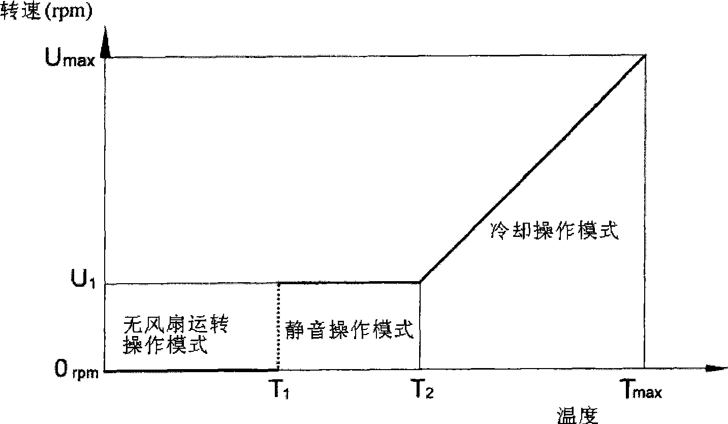
[0074] Please refer to Figure 3A , which is a schematic diagram of the rotational speed of the motor and the temperature inside the closed casing with the electronic system in the first preferred embodiment of the present application. Such as Figure 3A As shown, the vertical axis represents the rotational speed of the motor, and the horizontal axis represents the temperature detected by the temperature sensor. In this embodiment, the motor has three modes of speed control, including: a fanless operation mode, a silent operation mode and a cooling operation mode. When the temperature inside the closed casing with the electronic system is lower than a first threshold temperature (threshold temperature) T...


PUM


Abstract

The invention provides a motor speed control method, which comprises the following steps: when temperature in a closed housing provided with an electronic system is lower than a first critical temperature, the motor is operated under a none-fan operation mode, wherein, the speed of the motor under the mode is zero; when the temperature in the closed housing provided with the electronic system is higher than the first critical temperature and lower than a second critical temperature, the motor is operated under a mute operation mode, wherein, the speed of the motor under the mode is a fixed speed; and when the temperature in the closed housing provided with the electronic system is higher than the second critical temperature, the motor is operated under a cooling operation mode, wherein, the speed of the motor under the mode is the function of the second critical temperature, and moreover, the speed of the motor is operated between a maximum speed and the fixed speed. The motor speed control method can save energy, reduce noise, improve power loss and increase power efficiency.

Description

technical field [0001] The invention relates to a motor speed control, especially a method applied to the motor speed control, wherein the motor speed is adjusted and controlled according to the temperature near the heating element, and the fan driven by the motor is used to cool down the heat generation The proximity temperature of the component. Background technique [0002] When many electronic devices are in operation, heat and high temperature will be generated due to the heating elements contained in the electronic system in the electronic device. To cool heat-generating components of an electronic system, a fan is most commonly used to dissipate hot air within an enclosed enclosure of an electronic device. Generally speaking, for personal computers, servers or similar products, as the usage frequency or load of the central processing unit (CPU) increases, the temperature of the central processing unit (CPU) will rise. Therefore, computers, servers, or similar produc...

Claims


Application Information

Patent Timeline
Patent Type & Authority Applications(China)
IPC IPC(8): G05D23/19G05D23/185
Inventor 张修诚
Owner SEA SONIC ELECTRONICS
Why Eureka
Try Eureka